HW Mod SwB
The SwB switch is connected to the CPU pin capable of analog input,
so it can be replaced with a three-position switch instead of two-position
one. It can also be handled as a six-position auxilliary channel
in combination with the SwA switch. See the Key ⭢ AUX Channels menu.
- A three-position switch
- A 4K7 resitor, SMD 1206 or 0804 size
Firstly, the schematics looks as follows:

From this the R18 and R30 resistors are already in place, and it is
necessary to solder a new 4K7 resistor to the pair of empty pads
labeled C22:
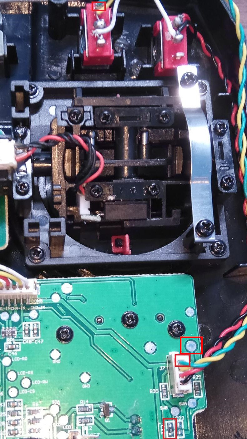
Replace the two-position SwB switch with the three-position one.
Add the third wire to SwB (the green one in the above image) and
connect it to the connector J7 as described.
Alternatively, it is possible to solder it to the circular pad upper
right from to the connector - it is the same wire/net.
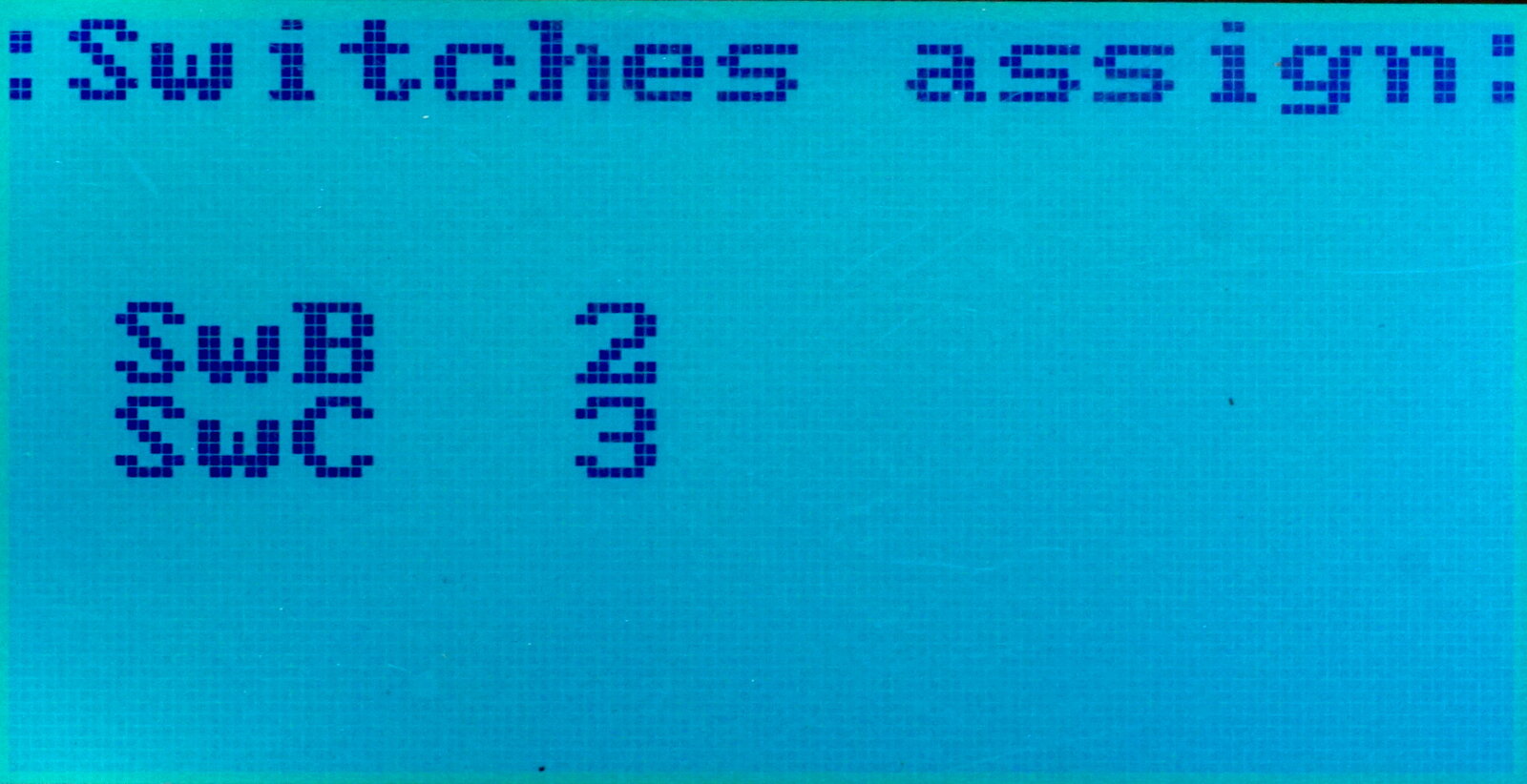
In the System ⭢ Extra ⭢ SwB+C menu, configure SwB for three positions: