For basic testing and implementation of TMP117 sensor
-
Based on: SparkFun_TMP117_Arduino_Library
-
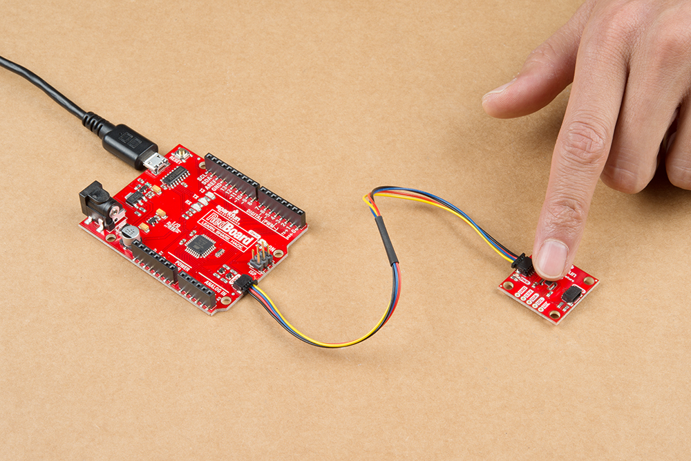
See the SparkFun tutorial
This code is specific for boards with ATmega328 such as UNO, Nano, Pro Mini.
- The ATmega328 has a very useful function for this emulator that allows ignoring some bits of the I2C address in slave mode. So the I2C module accepts commands from different slave addresses.
The TWAMR can be loaded with a 7-bit slave address mask. Each of the bits in TWAMR can mask (disable) the corresponding address bits in the TWI Address Register (TWAR). If the mask bit is set to one then the address match logic ignores the compare between the incoming address bit and the corresponding bit in TWAR.
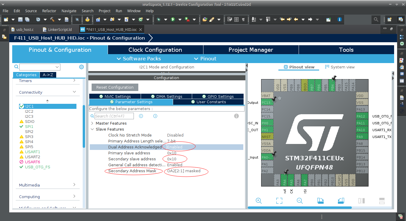
Note: Apparently the MCU STM32 also supports this feature of masking the I2C slave address:

The code can be adapted for other boards, but it will probably only recognize one slave address at a time, such as the ESP32 board, when researching I found references that the I2C hardware does not support this functionality.
Available implementations:
- Four active addresses (0x48/0x49/0x4A/0x4B)
- I2C bus speed 400kHz
- Read registers
- Write registers (Do not change EEPROM1, 2 and 3 if not really necessary)
- Use the Arduino board's real EEPROM to save data
- Emulated temperature value can vary automatically
- Emulated temperature controlled by analog input (A0/A1/A2/A3)
- Alarm flags and output pin (LED led on digital pin 13). Beware of voltage systems below 5V, this pin can force 5V.
Communication operation:
- The slave address must be previously selected before the other operations
- For the slave address to be selected, carry out a transmission without sending additional data
- To do this, just start a transmission and finish it, it also serves to test the presence of the device on the bus
Working example found in the SparkFun library (SparkFun_TMP117.cpp):
  //make sure the TMP will acknowledge over I2C
  _i2cPort->beginTransmission(_deviceAddress);
  if (_i2cPort->endTransmission() != 0)
  {
    return false;
} //make sure the TMP will acknowledge over I2C
Wire.beginTransmission(_deviceAddress);
if (Wire.endTransmission() == 0)
{
// Other read or write operations here
}Note: Some functions were not implemented, such as these ones:
7.5.3.1.5 SMBus Alert Function: The TMP117 supports the SMBus alert function. When the ALERT pin is connected to an SMBus alert signal and a master senses that an alert condition is present, the master can send out an SMBus ALERT command (0001 1001) to the bus. If the ALERT pin is active, the device acknowledges the SMBus ALERT command and responds by returning the slave address on the SDA line. The eighth bit (LSB) of the slave address byte indicates if the alert condition is caused by the temperature exceeding T(HIGH) or falling below T (LOW). The LSB is high if the temperature is greater than T(HIGH), or low if the temperature is less than T(LOW). See Figure 7-11 for details of this sequence. If multiple devices on the bus respond to the SMBus ALERT command, arbitration during the slave address portion of the SMBus ALERT command determines which device clears the alert status of that device. The device with the lowest two-wire address wins the arbitration. If the TMP117 wins the arbitration, the TMP117 ALERT pin becomes inactive at the completion of the SMBus ALERT command. If the TMP117 loses the arbitration, the TMP117 ALERT pin remains active.
7.5.3.1.6 General-Call Reset Function: The TMP117 responds to a two-wire, general-call address (0000 000) if the eighth bit is 0. The device acknowledges the general-call address and responds to commands in the second byte. If the second byte is 0000 0110, the TMP117 internal registers are reset to power-up values.
Some monitoring and debug outputs can be done in the Serial Monitor of the Arduino IDE.
SparkFun's library has other useful examples as well. The example added here has been modified to demonstrate some additional functions of the TMP117, like for example reading UID (The other sensor, DS18B20, also has a UID type serial number, but it is not possible to change it, a unique 64–bit code stored in ROM).
A unique ID is also programmed in the general-purpose EEPROM locations during production. This unique ID is used to support NIST traceability. The TMP117 units are 100% tested on a production setup that is NIST traceable and verified with equipment that is calibrated to ISO/IEC 17025 accredited standards. Only reprogram the general-purpose EEPROM[4:1] locations if NIST traceability is not desired.
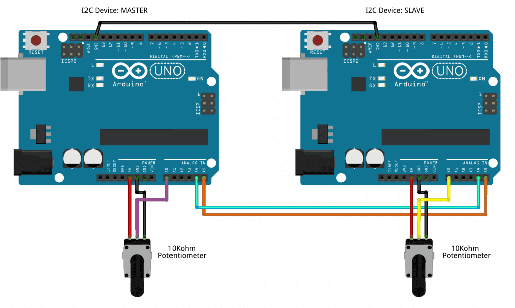
See this tutorial: How to Setup I2C Communication on the Arduino
For testing, a UNO board was used as a TMP117 emulator (I2C slave), and a Nano board as a I2C master. Using a 4k7 pull-up resistor on SDA and a 4k7 resistor on SCL.
The TMP117 is a high-precision digital temperature sensor. It is designed to meet ASTM E1112 and ISO 80601 requirements for electronic patient thermometers. The TMP117 provides a 16-bit temperature result with a resolution of 0.0078 °C and an accuracy of up to ±0.1 °C across the temperature range of –20 °C to 50 °C with no calibration. The TMP117 has in interface that is I2C- and SMBus™-compatible, programmable alert functionality, and the device can support up to four devices on a single bus. Integrated EEPROM is included for device programming with an additional 48-bits memory available for general use.
The low power consumption of the TMP117 minimizes the impact of self-heating on measurement accuracy. The TMP117 operates from 1.7 V to 5.5 V and typically consumes 3.5 µA.
For non-medical applications, the TMP117 can serve as a single chip digital alternative to a Platinum RTD. The TMP117 has an accuracy comparable to a Class AA RTD, while only using a fraction of the power of the power typically needed for a PT100 RTD. The TMP117 simplifies the design effort by removing many of the complexities of RTDs such as precision references, matched traces, complicated algorithms, and calibration.
The TMP117 units are 100% tested on a production setup that is NIST traceable and verified with equipment that is calibrated to ISO/IEC 17025 accredited standards.
For cases when system calibration is not planned, TI recommends not soldering the thermal pad to the PCB. Due to the small thermal mass of the device, not soldering the thermal pad will have a minimal impact on the described characteristics. Manual device soldering to the PCB creates additional mechanical stress on the package, therefore to prevent precision degradation a standard PCB reflow oven process is highly recommended. (DS pg. 36)
Software:
This library is free software; you can redistribute it and/or modify it under the terms of the GNU Lesser General Public License as published by the Free Software Foundation; either version 2.1 of the License, or (at your option) any later version.
This library is distributed in the hope that it will be useful, but WITHOUT ANY WARRANTY; without even the implied warranty of MERCHANTABILITY or FITNESS FOR A PARTICULAR PURPOSE. See the GNU Lesser General Public License for more details.
You should have received a copy of the GNU Lesser General Public License along with this library; if not, write to the Free Software Foundation, Inc., 51 Franklin St, Fifth Floor, Boston, MA 02110-1301 USA

