This repository contains the code for an Infinity Cube based on the ESP8266 microcontroller and NeoPixels.
- Introduction
- Features
- Hardware Requirements
- Quickstart
- Installation of Libraries
- Upload program to ESP8266 with Arduino IDE
- Resetting the Wi-Fi configuration
- Remark about Logging
- Contributing
- License
- References
The Infinity Cube is a mesmerizing LED cube based on NeoPixel LEDs and 3D printered parts. The original design of the cube is create by James. The stand is inspired by the design from here but adjusted to hold an button and reduced printing time. This repository completes completes the design with a software for ESP8266 to run and control the infinity cube.


infinity_cube_02.mp4
- control NeoPixel LEDs with ESP8266
- use seven predefined color modes
- one dynamic color shift mode
- change modes via press on physical button
- Wi-Fi connectivity for compehensive remote control via web interface
- time update via NTP server
- automatic summer/wintertime change
- easy Wi-Fi setup with WiFiManager
- configurable night mode (start and end time)
- customizable colors via webinterface
- ESP8266 (Wemos D1 mini) (Amazon*)
- 156x NeoPixel WS2812B LED-strip 60/m (Amazon*)
- push button with LED (Amazon*)
- USB-C female connector (Amazon*)
- micro-USB male connector (Amazon*)
- USB-C cable (Amazon*)
- USB power supply (5V/3A) (Amazon*)
- 3D printed parts (see 3d-printing-files)
- Connecting wires and soldering tools
*The links are affiliate links. The offers do not come from me, however, I receive a commission through the reference, if then a purchase takes place, but without you incurring additional costs.
- Clone the project into the sketch folder of the Arduino IDE
git clone https://github.com/techniccontroller/infinity_cube_esp8266.git- Install the required libraries: Installation.
- Upload the program to the ESP8266 as usual: Upload program to ESP8266.
- The implemented WifiManager helps you to set up a Wi-Fi connection with your home Wi-Fi -> on the first startup it will create a Wi-Fi access point named "infinitycubeAP". Connect your phone to this access point and follow the steps which will be shown to you.
- After a successful Wi-Fi setup, open the browser and enter the IP address of your ESP8266 to access the interface of the webserver.
- Here you can upload all files located in the folder "data". Please make sure all icons stay in the folder "icons" also on the webserver.
- Open http://<ip-address>/fs.html in a browser
- Upload fs.html
- Upload style.css
- Upload index.html
- Create a new folder icons
- Upload all icons into this new folder icons


Please download all these libraries as ZIP from GitHub, and extract them in the libraries folder of your Sketchbook location (see File -> Preferences). You can also install them via the Library Manager in the Arduino IDE.
- https://github.com/adafruit/Adafruit-GFX-Library
- https://github.com/adafruit/Adafruit_NeoPixel
- https://github.com/tzapu/WiFiManager
- https://github.com/adafruit/Adafruit_BusIO
The folder structure should look like this after installation:
MySketchbookLocation
│
└───libraries
│   └───Adafruit-GFX-Library
│   └───Adafruit_NeoPixel
│   └───WiFiManager
│   └───Adafruit_BusIO
│
└───infinity_cube_esp8266
    │   infinity_cube_esp8266.ino
    │   (...)
    |
    └───data
        │   index.html
        |   (...)
        |
        └───icons
First, the latest version of the Arduino IDE needs to be downloaded and installed from here.
To program the ESP8266 with the Arduino IDE, you need to install the board information first in Arduino IDE. To do that follow the following instructions:
-
Start Arduino IDE and open the File > Preferences window.
-
Enter http://arduino.esp8266.com/stable/package_esp8266com_index.json into the Additional Board Manager URLs field. You can add multiple URLs, separating them with commas.

-
Open Boards Manager from Tools > Board menu and search for "esp8266".
-
Click the install button.
-
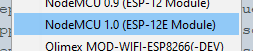
Don’t forget to select your ESP8266 board from Tools > Board menu after installation (e.g NodeMCU 1.0, or LOLIN(WEMOS) D1 mini (clone)).
-
Open
infinity_cube_esp8266.inoin Arduino IDE -
Connect ESP8266 board with Computer
-
Select right serial Port in Tools > Port
-
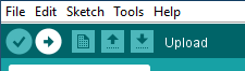
Click on the upload button in the Arduino IDE to upload the program to the ESP8266 Module.
You can clear the stored Wi-Fi credentials and restart the Wi-Fi setup described above with these steps:
- Open the settings panel in the web UI.
- Enable 'Reset Wi-Fi' slider.
- Save settings.
- LED test should be performed.
- Disconnect and reconnect the power. Wi-Fi credentials were removed. The setup should be restarted. Resetting the wifi credentials does not delete uploaded files.
The infinity cube sends continuous log messages to the serial port and via multicast UDP. If you want to see these messages, you have to
- open the serial monitor in the Arduino IDE (Tools -> Serial Monitor). The serial monitor must be set to 115200 baud.
OR
- run the following steps for the multicast UDP logging:
- Starting situation: ESP8266 is connected to WLAN, a computer with installed Python (https://www.python.org/downloads/) is in the same local area network (WLAN or LAN doesn't matter).
- Open the file
multicastUDP_receiver_analyzer.pyin a text editor and in line 81 enter the IP address of the computer (not the ESP8266!).
# ip address of network interface
MCAST_IF_IP = '192.168.0.7'- Execute the script with following command:
python multicastUDP_receiver_analyzer.py-
Now you should see the log messages of the ESP8266 (every 5 seconds a heartbeat message and the currently displayed time). If this is not the case, there could be a problem with the network settings of the computer, then recording is unfortunately not possible.
-
If special events (failed NTP update, reboot) occur, a section of the log is saved in a file called log.txt. In principle, the events are not critical and will occur from time to time, but should not be too frequent.
Contributions are welcome! Please fork this repository and submit a pull request with your improvements.
This project is licensed under the MIT License. See the LICENSE file for details.