Universal Data Logger using the internal ESP8266 flash memory and a large RAM cache

Minimal test setup, D1 mini on the left and DS1307 realtime clock module on the right
Description: The ESP8266 has typically, depending on versions, 4 MB of internal flash memory for the program data some of which (1 MB to 3 MB) can be used to install a file system for user data. Previously the popular file system was SPIFFS which is now obsolete/deprecated and replaced by LittleFS. It has useful features such as wear levelling and is resistant against power failure due to some redundance. It is seducing to consider using the internal flash memory for data logging since e.g. 2MB could theoretically hold the weather record for many years. However, problems remain when frequently little portions of data are appended. Keep in mind that flash memory requires an entire block to be written at each write access which seems to be 8 kB in our case. Hence even though wear leveling would spread the data evenly over the whole range, the metadata that is generated by the file system to keep track of where the data is located, in case of data logging, is non negligible and can exceed the net amount of data. On some platforms it seems to be possible to configure LittleFS to cache up to 256 Byte of data by itself before a write access. Caching always comes at the expense of power fail safety since data that is cached but not yet on the non-volatile memory would be lost in case of a power failure. Here we sacrify power fail safety in order to reduce write cycles and the cost of excessive metadata that would slow down file access. Therefore, this program caches by itself a large amount e.g. 8 kB of data before a write access is performed. However during a controlled shutdown the program forces saving even a partially filled cache to the flash memory. The power fail resistance of LittleFS is only maintained to the extent that an unexpected power failure would not corrupt the file system as such, but the cached data will be lost. The user either has to provide other means of power fail safety, i.e. power management that performs a controlled shutdown as the battery gets low, or must bear with loosing a certain amount of log entries.
Applications: Use cases in research and engineering, industry, agriculture, logistics, social science and big data, sports/outdoor/leisure activity etc.: anything from GPS tracking, weather recording, measurement data acquisition, person or vehicle counting, supply chain monitoring, error log, power glitch monitoring, intrusion logging, fitness tracking, machine wear and maintenance reminder, or even a model aircraft flight data recorder !
Legal Disclaimer: This hobbyist project is not designed for medical or life sustaining systems, passenger vehicle control, or anything else required to be fail safe, and comes with absolutely no warranty. Use at your own risk and feel free to adapt and improve.
Requirements:
Software:
Arduino IDE
LittleFS library
ESP8266 core installed in IDE board manager
LittleFS sketch data uploader plugin is not required here
Hardware:
ESP8266 board, recommended is the Wemos D1 mini and its chinese clones
Realtime clock module DS1307
CR2032 button cell battery for the clock (well, it can run without, but the realtime is lost upon shutdown)
Pushbutton to manually trigger shutdown and save data when data logger is used without PC
Wire diagram:
Wemos_D1_mini-------DS1307 RTC module
5V----------------------VCC
G-----------------------Gnd
D1----------------------SCL
D2----------------------SDA
Wemos_D1_mini-----------Pushbutton
D0--------------------------Pin1
D5--------------------------Pin2
Usage:
Before uploading the sketch to the ESP8266, the user must define the size of memory reserved for the file system in the IDE under Tools -> Flash size. I recommend 2 MB for a Wemos board with a total flash memory of 4 MB. To convert the universal data logger into something usefull, the user shall add his/her own code into the main loop to collect sensor data or accept other external input, concatenate the desired log entry message into a char array "userdata" (max 180 characters) and call the function cachedata(userdata) to generate an entry preceded by a timestamp and terminated by a carriage return. The program automatically handles caching and flash writing to the file log.txt. It communicates with the command prompt by USB serial, the port set to 9k6 8N1, and commands are described in the help screen (typing "help") which also shows up at startup. The data logger can run as standalone device on a USB powerbank without a computer. It is important to shut down the data logger by the hardware button before removing the powerbank, to force writing the cached data (which can be huge!) to the nonvolatile flash memory. For increased protection against loss of data, it is further recommended to built a power supply whose battery voltage can be monitored by the ESP8266, allowing to shut down safely when the battery goes low.
Remark about Realtime clock supply voltage and incompatibility between 3V3 and 5V logics:
Actually the clock module is a 5V version and must be powered from the 5V rail of the Wemos board, otherwise it would suspend I2C data transfer while a button cell battery is inserted, see https://www.arduinoslovakia.eu/blog/2017/10/ds1307-a-esp8266?lang=en Consequently, its input and outputs will then be at 5V logic levels and if connected to the 3.3V logic of the ESP8266, it is, strictly speaking, running somewhat out of specifications. However, i have not experienced issues with such configurations. If the Wemos board is USB powered from 5V, it has typically a lower 4.4V on its 5V rail due to the voltage drop of its internal diode. Furthermore, each I2C device has its clock and data open drain terminals pulled up to its respective VCC by a high impedance resistor of typically 10 kOhm. So the two I2C devices in parallel would pull up their terminals to a mean VCC of 3.85 V with an effective 5 kOhm resistor. On one hand, this is not enough to physically damage the ESP8266 with its 3.3V logic, and on the other hand, a high level issued by the ESP8266 is sufficiently high to be recognized as such by the RTC module. In conclusion, the I2C standard with its open drain terminals is more tolerant to mixing 5V and 3.3V logic than for example RS232. If you are uncomfortable with such a setup, the workaround is to replace the clock module with a different one, which would however be likely to multiply the cost and size of the project.
The command prompt
At startup, the datalogger displays the online help, file system info, current date & time, and the default log file

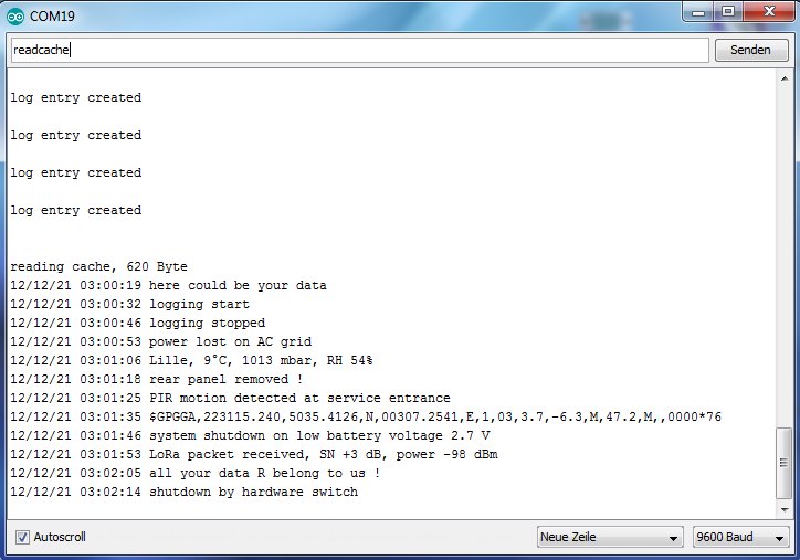
Let's create some "imaginary" log entries with the command customentry, and then use the readcache command to display the content of the cache :
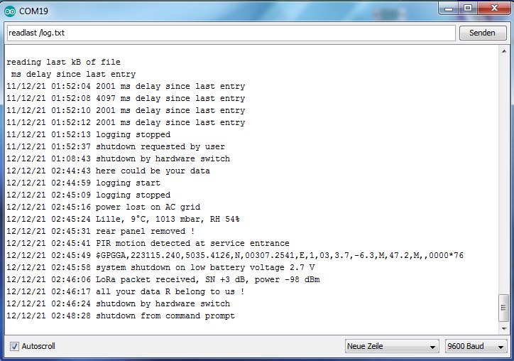
then, after using a commit command or shutting down the data logger safely by the shutdown command or hardware button and restarting, we use the readlast command to read out the last kB of the log file from the flash memory. After previous entries created by the test routine, our manual log entries appear now appended to the file on flash memory.