You signed in with another tab or window. Reload to refresh your session.You signed out in another tab or window. Reload to refresh your session.You switched accounts on another tab or window. Reload to refresh your session.Dismiss alert
its xsi and eta coordinates are both defined in the wing component segment as it is the parent of the control surface
the eta position of the innerHingePoint and outerHingePoint is determined by the outerShape element -> innerShape/outerShape -> etaLE (etaTE does not influence this coordinate, i.e. no interpolation between LE and TE position)
the xsi position (hingeXsi element) is measured from the leading edge of the parent wing structure
the z-position of the hing line is specified by the hingeRelHeight element which refers to the local thickness of the wing at the hinge point position (0 = lower skin; 1 = upper skin)
Problem description
The hinge line cannot be outside of the parent wing geometry, because:
eta, xsi and hingeRelHeight may only take values between 0 and 1 and must therefore be within the parent wing geometry
Certain configurations are not possible to model with the current definition, e.g.:
Canard wings: hinge line is out of the parent wing geometry and the hinge line could be better described by a hinge point and direction vector [Quora; accessed 17-04-2020]
Solution
... will be documented in this issue. Any suggestions welcome.
Current problems to consider in this context:
if possible: remain backwards compatible (i.e., additional elements, avoid changes to current definition)
in case of an additional offset vector:
implicitly fix the origin hinge line to reduce ambiguity?
relative coordinates (less problems with scaling of geometry) or absolute coordinates to be consistent with hinge line translation in the step definition?
is an additional eta translation necessary for the hinge point? (could solve the problem to define a hinge line which is inside of a canard wing geometry)
The text was updated successfully, but these errors were encountered:
Current state
pathelement by aninnerHingePointand andouterHingePointxsiandetacoordinates are both defined in the wing component segment as it is the parent of the control surfaceetaposition of theinnerHingePointandouterHingePointis determined by theouterShapeelement ->innerShape/outerShape->etaLE(etaTEdoes not influence this coordinate, i.e. no interpolation between LE and TE position)xsiposition (hingeXsielement) is measured from the leading edge of the parent wing structurehingeRelHeightelement which refers to the local thickness of the wing at the hinge point position (0 = lower skin; 1 = upper skin)Problem description
The hinge line cannot be outside of the parent wing geometry, because:
eta,xsiandhingeRelHeightmay only take values between 0 and 1 and must therefore be within the parent wing geometryCertain configurations are not possible to model with the current definition, e.g.:
tracks issue Kinematic description in controlSurfaceTrackTypeType for different steps along path #605 (@raedma): A configuration like trackType 2 subType2 is not possible
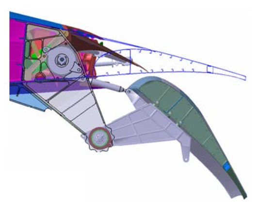
similar example [Strüber 2014]:

Canard wings: hinge line is out of the parent wing geometry and the hinge line could be better described by a hinge point and direction vector [Quora; accessed 17-04-2020]

Solution
... will be documented in this issue. Any suggestions welcome.
Current problems to consider in this context:
stepdefinition?etatranslation necessary for the hinge point? (could solve the problem to define a hinge line which is inside of a canard wing geometry)The text was updated successfully, but these errors were encountered: