Repository navigation
Home
Welcome to the bus-panel-driver wiki!
The panels have a 4 wire data cable which connects to a RS485 ALIKE driver (AMELI FY7000).
With the oscilloscope it was found that black is ground and white and brown alternate to be +5V relative to ground during a transmission. The delta between white and brown is therefor +5V or -5V.
In rest, they are both at zero.
This scope image composition shows the idle on the left and 3 bytes of data.
 With this we find that the baudrate is 600, that 1 startbit(St), 8 databits(0/1), 1 even parity(Pa) and 1 stopbit(Sp) are used.
We also find that the bus is not terminated with the RS485 resistors (2x120ohm). It is suspected that the receiver needs the full +-5V-swing to detect the bits.
The controller has its standard messages, but also a test-menu.
By reading the controller messages using a standard RS232 dongle, where white goes to pin2 and brown to pin5, we can use tio (or other serial program) to find the encoding of the messages.
tio -e -b 600 -d 8 -s 1 -p even --output-mode hex /dev/cu.usbserial*
Effect of displaying "Aalst Ekenrooi" and "1 't Goi"
  msg length  panel ?1      ?2  ascii text                                              end  check
===== ======= ===== =====   =========================================================   ===== ==
02 05 30=0x10  31   31 0d   53 "41 61 6c 73 74 20 45 6b 65 6e 72 6f 6f 69" 0d           02 03 30
02 05 32=0x12  32   34 0d   46 "41 61 6c 73 74 20" 0d 46 "45 6b 65 6e 72 6f 6f 69" 0d   02 03 6a
02 05 20=0x00  33   30 0d                                                               02 03 28

02 05 2b=0x0b  31   32 0d   58 "31" 0d 54 "27 74 20 47 6f 79" 0d                        02 03 3c
02 05 2b=0x0b  32   32 0d   58 "31" 0d 54 "27 74 20 47 6f 79" 0d                        02 03 3f
02 05 23=0x03  33   31 0d   58 "31" 0d                                                  02 03 4e
The controller alternates two messages and has to send to addresses 1, 2 and 3 (front, side and back). This lead us to this speculation of the format.
start*2 len addr layout 0d value 0d stop*2 xorcheck

start   02 05    stop   02 03

len     formula
hex     hex-0x20 = length

addr    mapping
31      sign 1
 :       :
37      sign 7
46      broadcast to all signs ???

layout  meaning     value
56      set level   30=auto  31-38=level 1-8
54      test        3131=allon 3132=alloff 3139=cyclic test 3030=stop
53      status req  no value
30      clear sign  no value?
31      display 1   1x text of font
32      display 2   2x text of fonts, one behind the other
34      display 2   2x text of fonts, below one another

font    number that influences size and thickness of the font
31 - 6f some duplicates, also not in a linear order
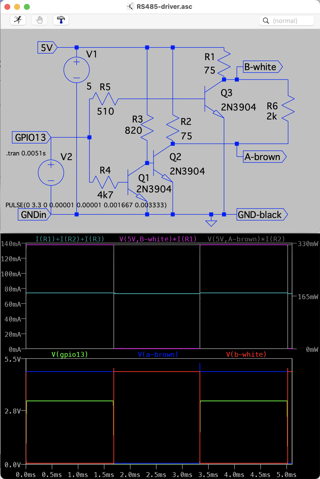
In order to send with an ESP32 we have devised this simple circuit that runs of a 3V3 logic port and uses the USB 5V to drive the A and B port alternately. It works fine but is rather wasteful. It would be able to drive the 2x120ohm of RS485, but since that is not used, in the future I would redesign something better, or even check out if a real RS485 driver works.

From here, you should read the source code to see how it uses the UART-library to send your preferred message to the panels.