Repository navigation
Radio Interface Hardware
Info about hardware to connect a DigiPi to a radio
There are two Digirig models: Digirig Mobile and Digirig Lite. Mobile includes CAT control for rigs that can be remote controlled. Lite is for rigs without CAT, it just provides the audio interface and PTT. Note that the "Lite" version isn't specifically supported on Raspberry Pi, possibly due to power concerns (you may have to use a powered hub). Get the "Mobile" product to be sure.
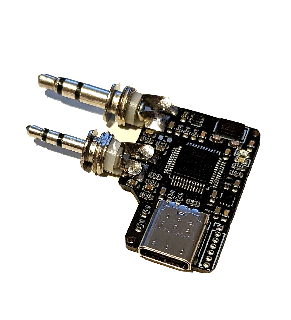
"All In One Cable" is a misnomer - it's not a cable, its a soundcard interface that can control PTT. It requires a USB cable.
An AIOC shows up as two device classes: an audio interface and a serial port. The serial port is used to control the PTT (Push To Talk).
PTT method DTR Port /dev/ttyACMO
Sources:
Try volume on the radio at almost max, then head into the Audio settings (alsamixer)...
Hit F5, set AIOC Audio In to 70, AIOC Audio In 1 to 70, AIOC Audio Out Volume to 84 and AIOC Audio Out Volume 1 to 84, then "Save Configuration" on the main screen or sudo alsactrl store if you are in Shell.
)
The AIOC thingies are super sensitive to RF. The issue is that most HTs use your body as the counterpoise through the frame. Unfortunately the AIOC couples far better even if you are holding the HT since it is directly grounded to the frame. Good antenna and lower power tends to help but it's still kind of hit or miss for me and since the whole thing plugs directly into the radio there's no way to get ferrites between the radio and the STM32 chip. It does help to put ferrites on the USB cable and use one with a right angle connector to prevent induced current in the USB line (i.e. don't have it parallel to the antenna) but the real issue for me seems to be the combination of a quarter wave whip and no counter. I can take the same setup that is latching the PTT, throw about a dozen ferrites on the USB cable and make no difference. Then just unhook the whip and hook it to a roll up J-pole antenna with some coax and it works great. Some people have made little extensions to go between the AIOC and the radio so they could choke it there and seem to have good luck too but I haven't tried that. I've also noticed it tends to happen less frequently on UHF than VHF
This summarizes observed power delivery issues while operating a Raspberry Pi 3B with a Tigertronics SignaLink USB interface. Note that this would also impact other versions of Raspberry Pi, with newer versions having greater impact due to higher power demands. Although a 5 V / 3 A power adapter was used, unstable operation was observed until power delivery was distributed across two separate power paths. The observations suggest that cable quality and voltage drop under load were significant contributing factors.
TLDR; Use a high quality USB cable rated for the Pi in use!
The Raspberry Pi Foundation recommends a regulated 5 V / 2.5 A power supply for the Raspberry Pi 3B. In addition to powering the board itself, the supply must also support connected USB peripherals. The Raspberry Pi 3B can receive power through:
The Micro-USB power connector The 5 V GPIO header pins The USB subsystem may provide up to approximately 1.2 A total to attached USB devices.
The Tigertronics SignaLink USB derives power directly from the Raspberry Pi USB connection. During transmit operations, additional interface circuitry becomes active, increasing total system load. The TNC is listed as max current draw of ~140ma on transmit, ~80ma nominal. https://tigertronics.com/slusbmain.htm
Initial testing used:
One 5 V / 3 A USB power adapter One Micro-USB power cable Despite the adapter being properly rated, system instability was observed. The most likely cause was voltage drop caused by a low-quality or undersized USB cable unable to reliably carry the required current.
Stable operation was eventually achieved by distributing the load across two separate power paths:
One 5 V / 3 A supply connected to the Raspberry Pi Micro-USB input One 5 V / 2.5 A supply connected to the Raspberry Pi GPIO 5 V rail No direct electrical measurements were performed; therefore, these observations are operational findings rather than verified electrical measurements.
The primary observation from testing was that cable quality is critical. Even when using a correctly rated 3 A power adapter, thin or low-quality USB cables may introduce enough voltage drop to cause instability.
Distributing the electrical load across two power input paths improved operational stability during testing. Additionally, using high-quality power cables rated appropriately for the expected current load is strongly recommended. The use of multi-path power via GPIO power injection bypasses several onboard protection components present on the normal power input path. Additional information and concerns here: https://www.tme.eu/en/news/library-articles/faq/page/76006/can-i-power-the-raspberry-pi-through-the-5v-pins-on-the-gpio-connector/