Repository navigation
4PDT Order Switcher
ℹ️ Note: This board hasn't been built yet, but its order switching and LED wiring were verified as part of another build.
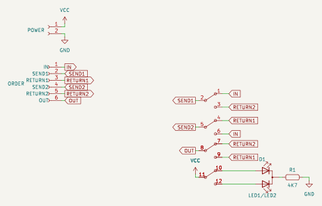
The 4PDT Order Switcher swaps the order of two effects with one toggle. In one position the signal runs IN > S1 > S2 > OUT, in the other IN > S2 > S1 > OUT. The fourth pole switches a bicolor LED so you can see which order is selected.
You can also use a 3PDT toggle in the first three columns of the switch footprint (pads 1-9) if you don't want the LED; leave D1 and R1 off. The 3PDT's bushing sits about 2.4 mm to the side of where a 4PDT's would, so drill the enclosure for the switch you use.
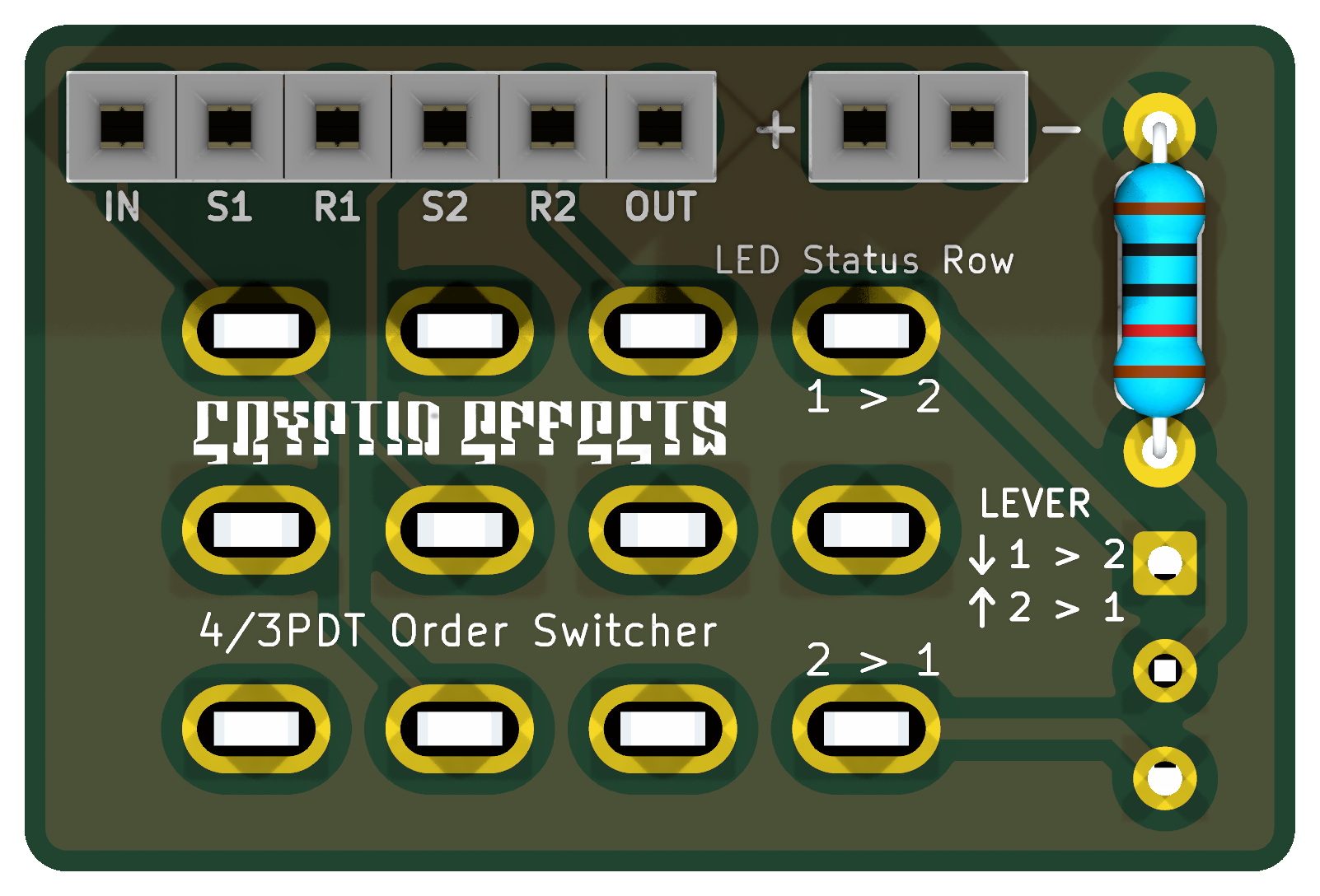
| Front | Back |
|---|---|
 |
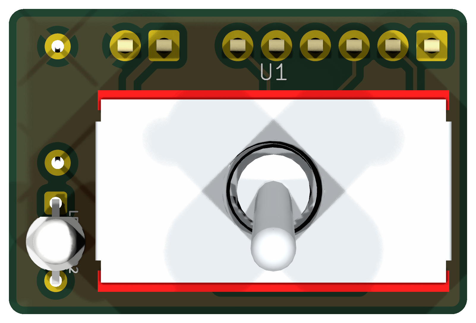 |
The back is shown as viewed from the back of the board. The board is 30 x 20 mm.
Gerbers: GERBER-4PDT-Order-Switcher-r2026-10-16.zip
| Pad | Connects to |
|---|---|
| IN | From the input (or the previous pedal stage) |
| S1 / R1 | Send to and return from effect 1 |
| S2 / R2 | Send to and return from effect 2 |
| OUT | To the output |
| + / - | 9 V for the LED |
| Component Name | Value | Note |
|---|---|---|
| R1 | 4k7 | LED current limiting resistor, choose to taste (2k2 for brighter) |
| Component Name | Value | Note |
|---|---|---|
| D1 | 3 mm bicolor LED | Common cathode (3 legs, cathode in the middle) |
| Component Name | Value | Note |
|---|---|---|
| U1 | 4PDT | On / on mini toggle (or a 3PDT, see the introduction) |
| J1 - POWER | 2 pin header | +9 V and ground, for the LED only |
| J2 - ORDER | 6 pin header | IN, S1, R1, S2, R2, OUT |
- The "1 > 2" and "2 > 1" labels next to the switch name the rows of lugs. The LEVER key on the front shows which way to throw the lever for each order: lever down gives S1 > S2, lever up gives S2 > S1. Toggles connect the row on the opposite side from the lever, so check one row with a meter if your switch is different.
- Which LED color goes with which order depends on the LED; turn it around to swap the colors.
- The LED only needs +9 V and ground; the audio path is entirely passive.

This layout is licensed with a Creative Commons BY-NC-SA 4.0 license (Attribution, Non-commercial, Share-alike).
- 2026.10.16 - First release. The board itself hasn't been built yet; the switch wiring was verified as part of another build.
Files for this board live in the main repository: Utility-Boards/4PDT-Order-Switcher/