Repository navigation
Hardware Woes
In addition to software issues with PWM, requiring an obscure patch be applied for the PWM sysfs interface to work, there are also hardware quirks. Namely, the PWM outputs on our Raspberry Pi 5 seem to have issues pushing the voltage low. For example, here is the output of hardware PWM0 on GPIO pin 18 with 20kHz frequency and 50% duty cycle:

You will notice that the output is more like 100% duty cycle, with the voltage barely changing from high. Very strange. Here is hardware PWM1 on GPIO pin 19 with the same settings:

This one at least moves downwards, but is obviously struggling. Each low period has an initial sharp drop in voltage, which suddenly turns into some sort of slow exponential decay to a voltage significantly higher than 0. This problem becomes more pronounced at higher duty cycles. See below with a 90% duty cycle:

Here, the voltage barely reaches half way to 0.
What's interesting is that the behaviour of the PWM output changes for the better when connected to the PWM input of the MD20 motor driver. Here is hardware PWM0 on GPIO pin 18 with 20kHz frequency and 50% duty cycle, as in the first image, but connected to the MD20 PWM input:

Now the voltage actually drops to 0, although it takes a while with a strange decay rather than a straight edge. Now see the same configuration with a 90% duty cycle

Again, the voltage fails to reach 0.
This strange behaviour turns out to not be too disruptive. The voltage drops far enough and fast enough when the duty cycle is below about 90%, that the PWM output of the MD20 motor driver is as expected. However, once the duty cycle reaches about 90%, the voltage does not drop far enough to be registered as a low level by the MD20, causing the MD20 to output PWM with a 100% duty cycle. Thus, only the very upper end of PWM duty cycle is adversely affected.
To be clear, the measurements taken above either had the pi's PWM output connected directly to the oscilloscope probe (also connected to a ground pin), or to the MD20 PWM input with the probe contacting the fastening screws (PWM input and ground). There were no other pins connected that could be fighting with the PWM output, unaccounted pull-up resistors etc.
To drive our reactions wheel, we used a 12V brushed DC motor with a 34:1 gearbox, giving a maximum speed of 350RPM and a stall torque of 12kg-cm. This was then driven with the MD20 PWM motor driver. The maximum (standard) output frequency of the MD20, 20kHz, was used. We expected that with this PWM frequency, and the large inductance of the motor being driven (measured at 1.9mH), that a direct connection of the MD20 to the motor would provide a sufficiently smooth current supply. A circuit schematic is given bellow, including the resistance of the motor and INA260 current sensor (used to measure the torque generated by the motor).

A plot of the current measured by the INA260 approximately every 4ms during testing with this configuration is shown below:

As it turned out, there was significant noise in the current supplied to the motor. This was resolved by adding an LC filter across the INA260 and motor. An inductor of 560uH and capacitor of 33uF were used, giving a cut-off frequency of about 7.36kHz to remove any 20kHz PWM switching noise or other, higher frequency noise. A circuit schematic is given below:

This provided the following measurement by the INA260 during testing:

The noise in the signal was significantly reduced.
After writing the top section of this page on the strange PWM output from our pi, it has since completely died for unknown reasons. There was no obvious miss-wiring to cause a short, and no visible damage on the pi. It was exhibiting other strange behaviour before kicking the bucket, such as randomly switching off for no reason, even with the motor circuitry unpowered. In fact, this is how it died. It switched off and never turned back on. Were were also having serious I2C reliability issues, perhaps these were related?
Some other strange behaviour occurred when probing the connections to the MD20 control inputs from the pi with an oscilloscope. Touching the connections with a probe would change the signal. For example, if the PWM connection was set to have a 50% duty cycle, touching with a probe would prevent the signal from fully dropping to 0, causing the MD20 output to run at 100% duty cycle. This did not happen all the time, hence the (kind of) working PWM oscilloscope images in the above PWM section. Touching a probe against the direction control connection could cause the motor to aggressively switch direction, where it would only rotate in one direction without the probe touching.
Our theories as to the cause of death are:
-
There was somehow a connection between the motor power circuitry and the pi. The only connections were via the MD20 motor driver (control ground, direction, and PWM) and INA260 (3.3V power, interrupt, I2C etc.) None of these should have a direct connection to the motor power circuitry. The MD20 was wired up as given in the data sheet (page 4), and the current through the INA260 has no direct connection to the logic circuitry (data sheet, page 12). Thus, it seems unlikely that this would be the cause.
-
At the beginning of the lab work, all of the wired connections from the pi GPIO pins were accidentally attached upside down. This was spotted when probing the PWM output, which had a weird wavy component to it. We're not sure how there was any output at all, given we were probing the wrong pin. This was noticed and rectified on the same day, but perhaps some improper connections caused just enough damage to create intermittent faults? Perhaps the complete death of the pi was a blessing is disguise.
An image of the dead pi is given below, with the red power indicator on.
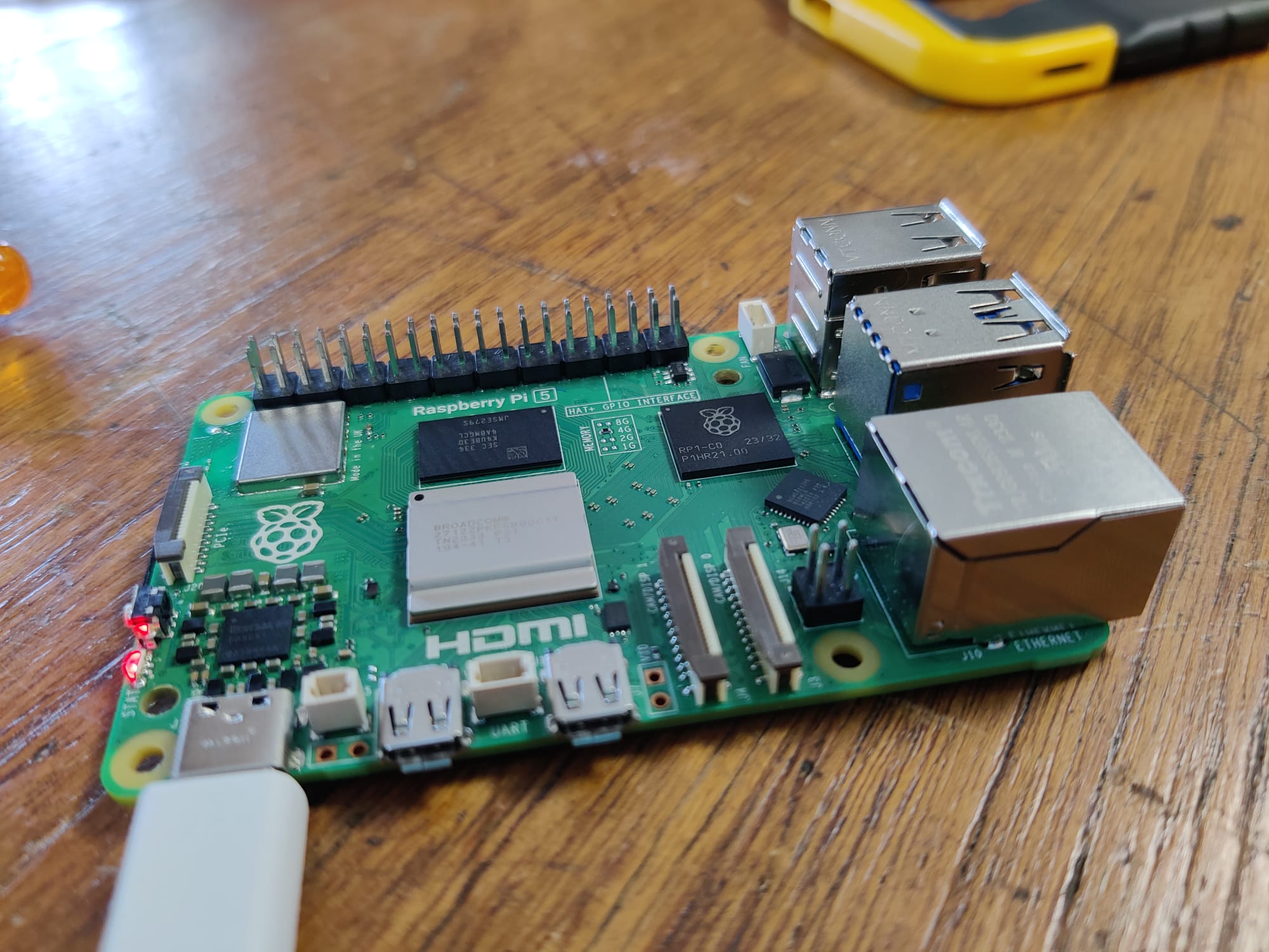
We have since obtained a new Pi 5. Its GPIO outputs have none of the issues mentioned above. The PWM output is a clean square wave. There is no funny behaviour when probing the connections to the MD20. The reliability of I2C communication with the MPU6050 and INA260 has improved greatly. The main issue now is the INA...
The INA260 has been placed as shown in the circuit diagram below, indicated by its approximate total package resistance of 4.5mOhm. The INA260 will work just fine, but only when the motor is being driven in one direction. Once the direction of the motor driver is switched, the INA260 stops functioning correctly, causing constant I2C errors when communicating with the Pi, making data reading impossible. We are not sure what the cause of this issue is, although it is almost certainly an error in our schematic and/or a miss-understanding of how the INA260 functions. It is not negative currents that are the problem, since the data sheet clearly advertises the ability to measure such currents (and we have done so ourselves). If we find a solution, it will be added here. If we do not find a solution soon (current date 2024-04-11), then we will need to try control using only the MPU6050, with no control specifically for the torque supplied by the motor.
An investigation on 2024-04-12 has revealed the likely cause of our problem with the INA260. The data sheet specifies that the absolute minimum common-mode voltage on the IN+ and IN- pins is -0.3V, and the maximum 40V. Recommended values are between 0V and 36V. Probing with an oscilloscope revealed that this was satisfied when the motor driver was working in the forward direction, but when the direction was flipped sharp PWM signal would appear on the pins, driving the voltage below -0.3V on the downswings. This was the likely cause of the unreliability of the INA, and has likely also damaged it. After using the INA in this configuration for some time, it at one point got extremely hot. After this heating event, the offset in the current measured by the INA increased to 5mA (the maximum according to the data sheet), where before it was reading 0mA.
To investigate this further, we ran some simulations using the Qucs-s circuit simulation tool using the ngspice simulation backend. The circuit schematic shown below represents the system when the MD20 is driving the motor in the forward direction:

A 2ms transient simulation of this system gives the following result, where the red line is the PWM supply, and the blue line is approximately the common-mode voltage on the IN+ and IN- pins of the INA260:

The common-mode voltage on the INA is always within the recommended 0-36V limits. What happens if we drive the MD20 in the backward direction? The circuit schematic below represents that system:

Again, a 2ms transient simulation of this system gives the following result, where the red line is the PWM supply, and the blue line is approximately the common-mode voltage on the IN+ and IN- pins of the INA260:

It can be seen here that the common-mode voltage on the INA has a significant PWM component that drives the voltage well below -0.3V, regularly. This is almost certainly what damaged our INA and made it unusable for our application with this circuit configuration. Such a shame we didn't run these simulations before building and running the circuit :)
In an attempt to rectify this issue, we tried moving the INA from between the motor and filter inductor to "under" the motor, with one pin connecting to the motor, and the other pin connected directly to the backward drive pin of the MD20. This is visualised below:

In theory, when the MD20 is operating in the forward direction the common-mode voltage on the INA pins should be close to 0. When operating in the backward direction the voltage should closely follow the PWM output of the MD20, which should range from 0-12V. However, once set up this way issues still persisted when running the MD20 in the backward direction, although I2C errors occurred far less frequently. Probing with an oscilloscope revealed that the approximate common-mode voltage on the INA pins did follow the PWM output of the MD20. However, this PWM signal had fairly significant overshoot during transitions. On downswings, the voltage could drop as low as -0.5V before stabilising to 0V, below the -0.3V absolute minimum. See the below capture from the oscilloscope:

This probably contributed to the continued miss-behaving of the INA, but damage from the past circuit configuration that drove voltages far below -0.3V with great regularity may also be to blame. Regardless, by this point in our testing the INA was no longer measuring current correctly. All measurements were 5mA with a bit of noise, even when the current through the INA was definitely greater than this.
Given the short time left before the deadline, there is not enough time to obtain another INA260 and design a circuit that doesn't damage it. Maybe the circuit topology just discussed would work if there were no prior damage to the INA, but the PWM overshoot makes this risky. The INA could also be placed in series with the supply to the MD20, rather than the motor directly. This would guarantee a safe voltage for the INA pins, but would only measure current in one direction, regardless of the direction of the motor. The current measured would also include current supplying any logic, LEDs etc. on the MD20, in addition to the motor current. Given the filters between the MD20 input and the motor, the current measured may not accurately represent the motor current, even disregarding the current supplying the MD20 itself.
With the time available, we plan on trying to get the cup-holder balancing using just the MPU6050 and the angular position that it measures. Given more time, we would probably try to find a circuit that works well with the INA260, or find an alternative current sensor that doesn't mind negative voltages. Our motor has a position encoder, so an alternative to measuring current to find motor torque could be using this encoder to measure reaction wheel angular acceleration to find torque. It is unlikely we could implement and test such an alternative with the time available.
Besides issues with the reverse bias voltage that fried the INA260 sensor, LC filter was disrupting the I2C communication between the MPU6050 and the Pi. After testing the issue, it became evident that it didn't happen due to any physical vibrations or loose wire connections, but due to electrical spikes of voltage and current during the sudden switching of the motor's direction of rotation and PWM duty cycle. Those spikes were causing a permanent error in communication that could only be fixed by power cycling the system and the sensor. Removal of the filter from the circuit eliminated this issue completely.
It is strongly suggested not to use the filter in your setup unless absolutely necessary for eliminating high-frequency current noise that prevents bringing the device to a steady state.
Metal bolts were attached along the outer radius of the wheel to increase generated torque. That moved the centre of mass towards the front of the table and way too high above the ground. This caused some balance issues as the table started tipping over. The issue can be fixed by placing additional heavy weight on the rear bottom part of the table's structure. Make sure that added weight is equally distributed between the left and right sides.
For us, the issue was solved by placing two metal choke inductors on each side of the table and fixing them to the central rod with tape.
3D-printed casing material has a very low coefficient of friction and a very small area of contact with the surface, so it is very slippery. To give the table more stability, it should stand on a rubbery surface (for us it was the bottom of a mouse mat), or some high-friction material should be glued to the bottom of the structure.
As it turned out, the material for 3D printing cannot withstand the torque that is applied to the wheel by the motor. After some time the wheel wears off and starts deattaching from the motor's shaft. The solution for us was glueing the wheel to the shaft with superglue. A better approach would be inserting a metal socket inside the wheel to increase rigidity.
Many. Carefully read data sheets, plan and simulate circuits before actually running them, have spare hardware, have a plan B. We could have wrote code for using the motor position encoder in parallel to writing the code for the INA260, even if we didn't think we would need it. Now that plan A using the INA260 has failed, we probably don't have enough time to write and test code using the position encoder.