Section 2.1 Assembly of the Y Unit Mounting the threaded Rods and Power Supply
|
|
|
|
|
|
|
|
|


-
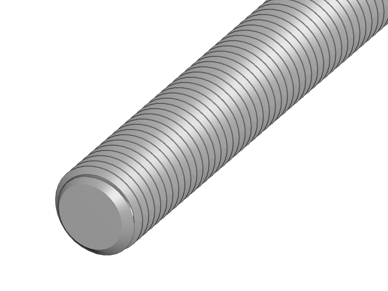
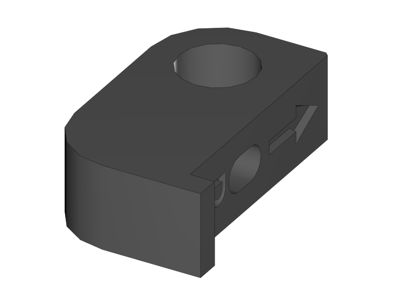
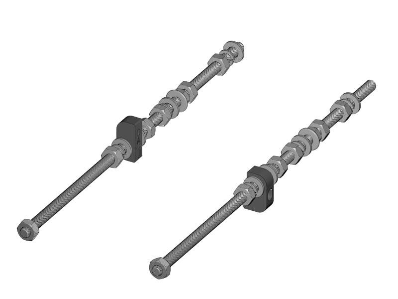
Slide the right Power-Supply mount onto the M10 rod.
-
Put a washer on both sides.
-
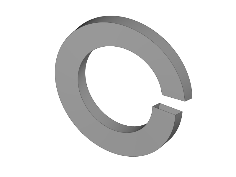
Two spring washers on both sides
-
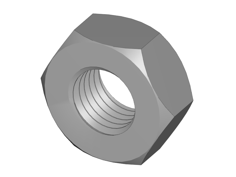
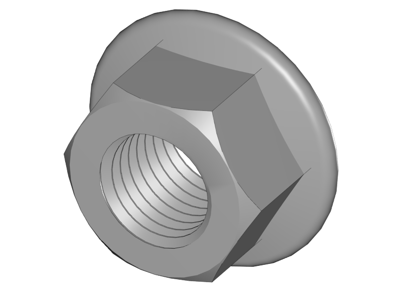
and two nuts on both sides.
-
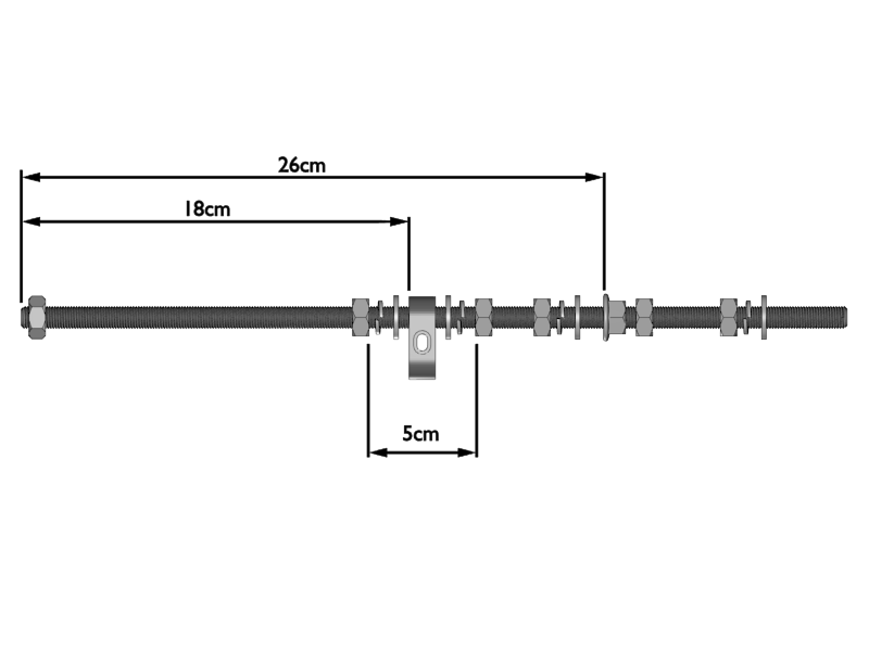
Do not make the nuts tight yet. Leave about 5cm place between the nuts.
|
|
|
|
|
|
|

-
Mount a nut, spring washer, washer and flange nut to the threaded rod for later mounting the XZ plate.
-
Also put an M10 nut on both ends for later mounting the front and back-plate.
-
Do not make anything tight yet.
|
-
The power-supply mount is about 18 centimeters from the front side of the rod.
-
The flange is about 26 centimeters from the front.
-
Don’t make this precise, measurements are just for reference for easier assembly later on.
|
|
|
|
|
|
|
|
|
|
|

-
Do the same for the left-hand rod.
-
Make sure that the orientation of the plastic parts is correct. The arrows should be pointing upwards.
|
|
|
|
|
|
|
|
|

-
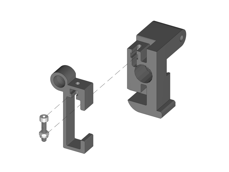
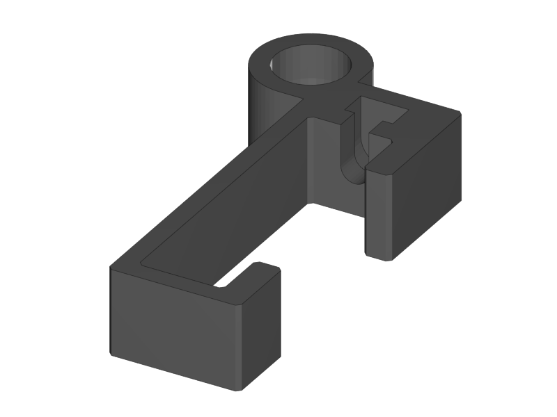
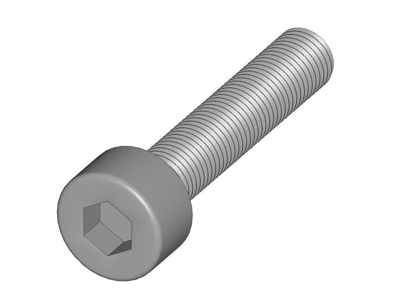
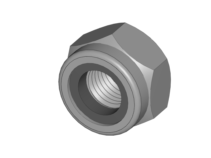
Turn the nut about 5mm onto the screw
-
Put the Y-Height Adjuster into the Y-FrontLeft part
-
Push the screw and nut into the slots of the plastic parts
-
Make sure the hexagon of the screw is reachable through the hole in the Height adjuster
-
Later this assembly will enable you to adjust the height of the smooth rod
-
|
|
|
|
|
|
|


-
Put the bearing with the two belt guiding discs into the slot of the front right Y-Corner.
-
Make sure the little notch of the discs is on the inside and the shiny side is point outwards.
-
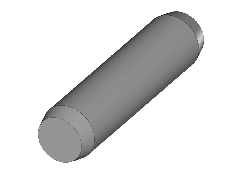
Slide in the dowel to fix the assembly.
|

-
Put the black sticker on the power supply to make it look nice.
|
|
-
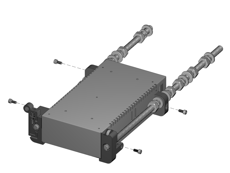
Mount the front Y mounts to the M10 rods.
-
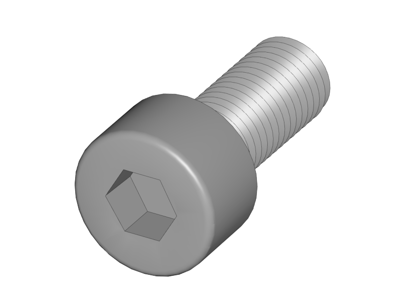
Mount the power-supply on the plastic parts with 4 M4 x 10 screws.
-
Note the air outlet of the power-supply will be facing downwards.
|
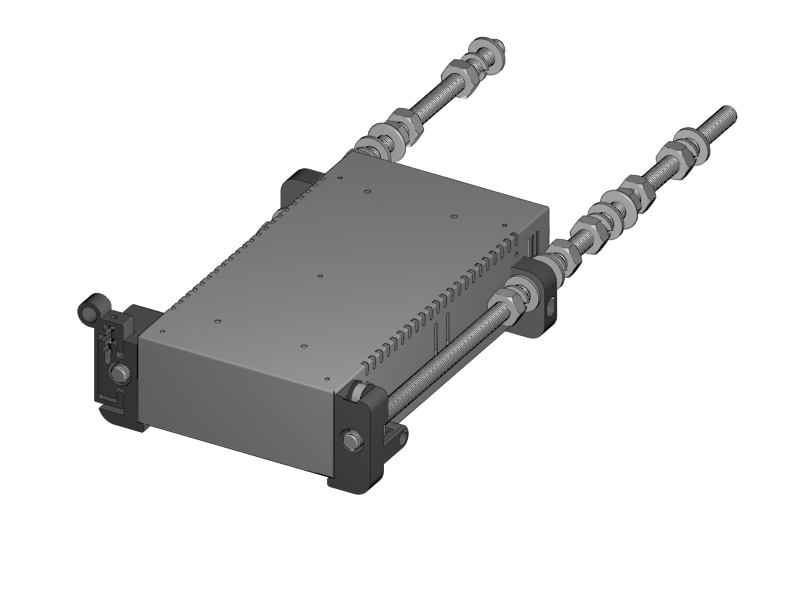
Great you now completed the first step of the assembly. Go on with the next step.