Section 3.2 Assembly of the XZ Unit Mounting the Z Axis
|
|
|
|
|
|
|


-
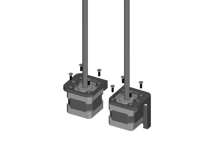
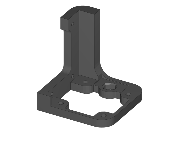
Mount the motors onto the holders.
-
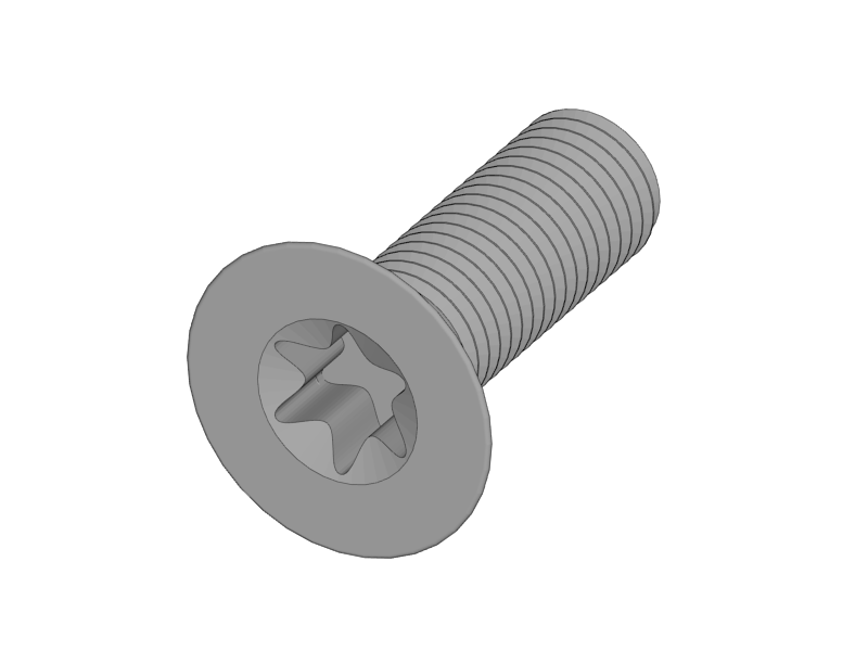
The counter sunk torx screws should be fixed with a Torx 10 screw bit.
-
-
Make sure the connector of the motor is at the back.
|
|
|


-
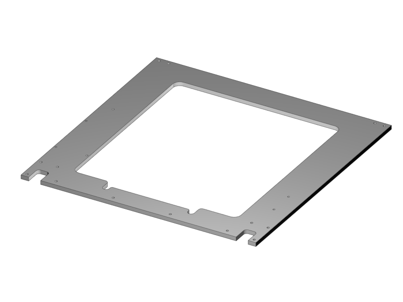
Mount the Z-Motors onto the XZ-Plate
-
Mind the orientation of all parts.
-
The engraved logo should be on the front
-
The left side of the aluminium plate has more holes than the right side.
-
Make sure that the connector of both motors is facing the aluminium plate.
-
-
Keep your aluminium free from scratches!
|
|
|
|
|
|
|
|
|
|
|
|
|
|
|
|
|


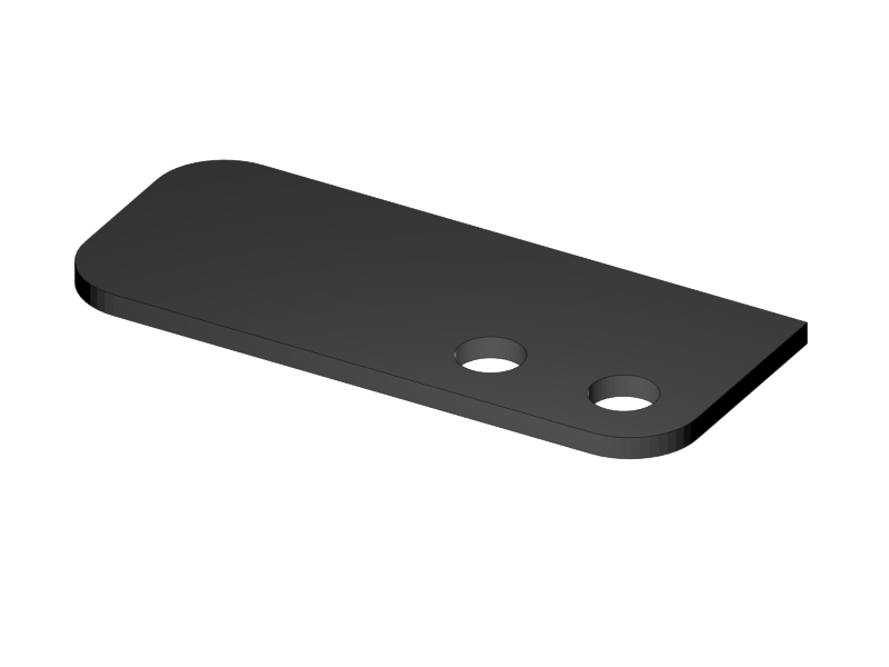


-
Put double sided tape on the shiny side of the Z Motor Covers, and attach them to it.
-
Alternative to double sided tape is plastic glue. Use only a little bit of it, so it is possible to remove the plate at some point in the future in case it is necessary.
-
-
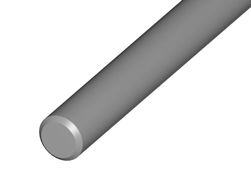
Push the smooth rods into the Z-Motor holders.
-
If it goes to stiff, use a handdrill to turn them in. Do not use a hammer.
-
-
Place the X-Bridge onto the smooth rods. Mind that the little hook on the X-Idler holder will be on the back side of the aliminium plate.
-
Carefully turn the ACME rods into the Nuts.
-
Put double sided tape on the shiny side of the X-Motor Cover and the X-Idler cover. Stick them onto the corresponding parts. The matte side should be visible.
-
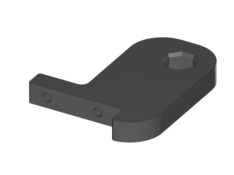
Push the Z-Top parts onto the smooth rods.
-
Mind that the shiny side of the printed parts is on the top.
-
-
Mount the top parts with the Torx screws. The long screws are in the outer holes.
-
Put double sided tape on the shiny side of the Z-Top part covers and stick them onto the parts.
|
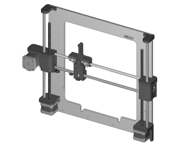
-
This is how the result looks like