Section 4.7 Wiring the Extruder
|
-
Connect the extruder motor with the remaining motor cables of 1 meter long.
-
Label all the wires in such a way that you will know which connector belongs to which wire.
-
Note: the left extruder is numbered "0", the right extruder is numbered "1".
-
Label all four heater cables as HE0 or HE1
-
Label the motor cables as E0 and E1
-
Label the termistor cables as T0 and T1
-
Label the Active fan as A-Fan
-
Label the Extruder cooler fans as E-Fan
-
-
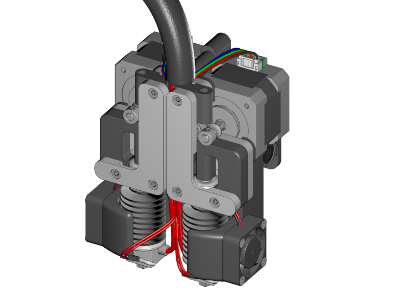
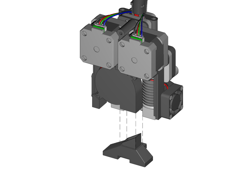
Lead all the wires through the thick braided sleeve.
-
Fix the braided sleeve onto the extruder unit with a zip tie.
|
-
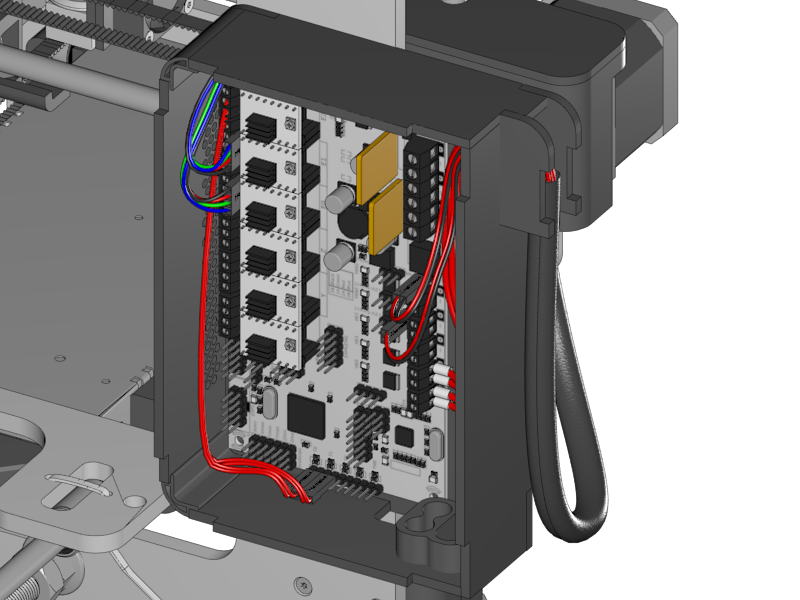
Lead the cable into the RUMBA case through the side inlet.
-
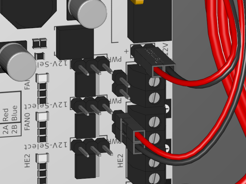
Connect the wires accordingly to the picture above. Detailed pictures will follow below.
|
-
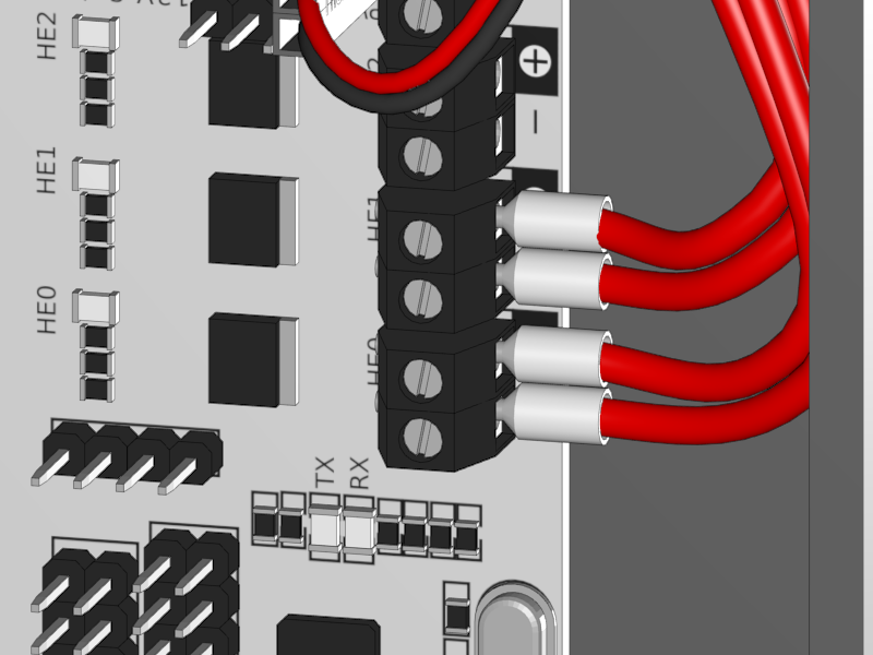
Connect the heaters to the HE0 and HE1.
-
Polarity is not important.
-
|
-
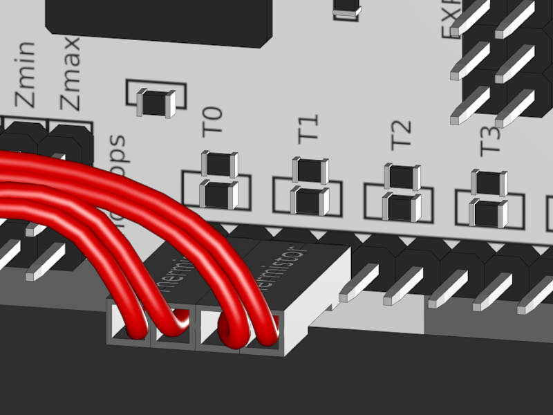
Connect the thermistors to T0 and T1.
-
Polarity is not important
-
|
-
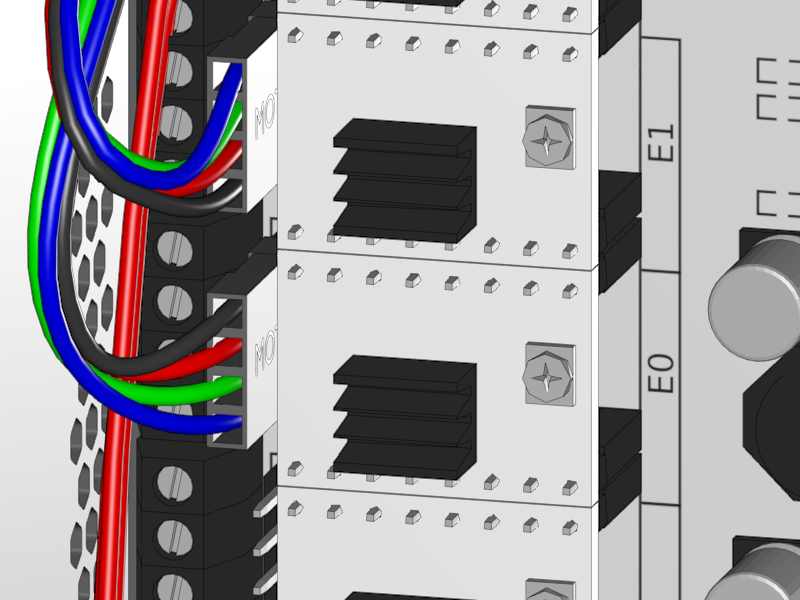
Connect the extruder motors to E0 and E1.
-
Note that the connectors are in a mirrored ordered.
-
In case the brand of the extruder motor is "Moons" note that the wire order is black red green blue or red yellow grey green.
-
|
-
Connect the Active Fan to the Fan 0
-
Note that the red wire is on the positive and the negative on the black
-
-
Connect the Extruder Fan(s) to the 12V output.
-
If you are building a dual extruder you will probably see a double wire for each pin.
-
Connect the red wire to the positive and the black to negative.
-
|
-
Put the extruder unit on a heat resistant surface.
-
Turn on the printer.
-
In the display menu push the button once and turn it to navigate to Control.
-
Continue to Temperature and Nozzle 0. And set the temperature to 150 degrees Celsius. Push the button once more to confirm.
-
The nozzle heats up now (be careful).
-
Note the first time the extruder heats up it produces some burning smells. This is nothing to worry about and also something that will soon go away.
-
-
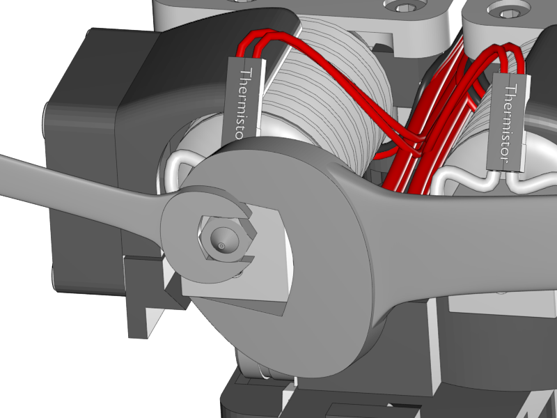
Wait until the temperature is stable for some minutes. Then increase the temperature to 280°C.
-
Wait until the temperature is reached and carefully fix the nozzle with a 17mm and 8mm wrench as shown above.
-
Let it cool down. Now test again if the heater still works (sometimes they break) by putting the temperature to 150°C (the nozzle should be colder than 150°C of course). If it heats up than everything is fine. If not, you’ll have to replace the heat cartridge.
-
Do the same for the right hand extruder.
-
remember the teflon inliner from the section 3.4: Assembling the Extruder? Once you are done unscrew the cooler body from the heatbreak and insert the teflon inliner.
|
|
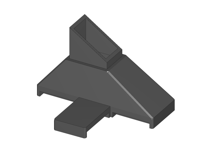
-
Slide the Active Cooling duct into the air outlet of the radial fan.
|
|
-
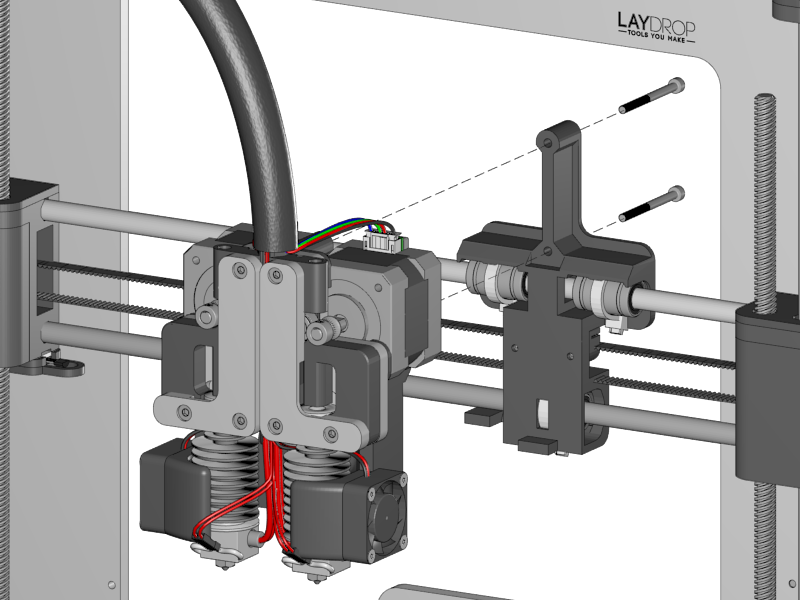
Put the extruder unit onto the X-Carriage.
-
Make sure that the cavity on the back of the cooling duct stands on the notch of the X-Carriage
-
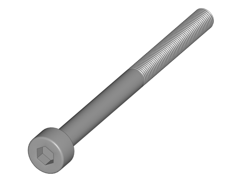
Fix the unit with the two screws
|
|
|
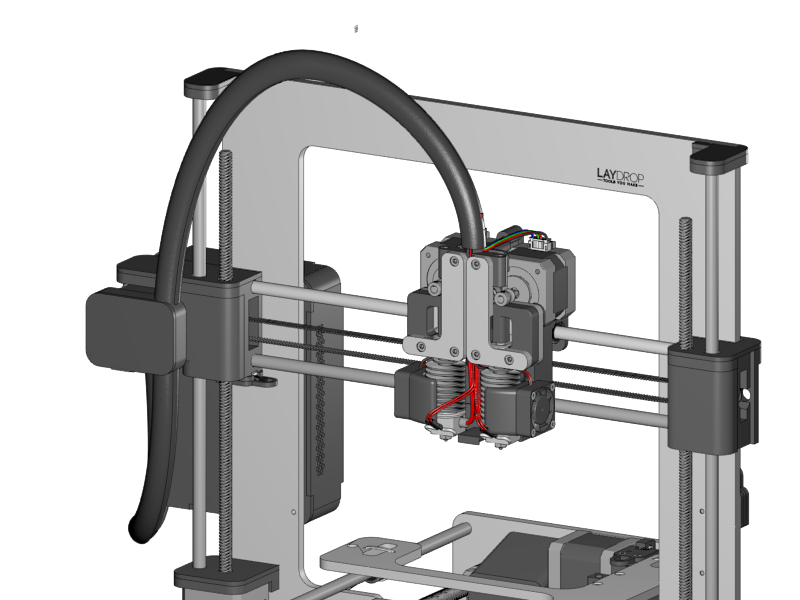
-
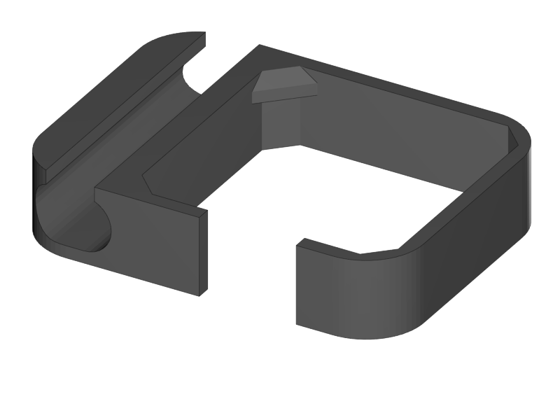
Put the braided sleeve into the opening of the Cable Holder.
-
Take care that the length is enough so the extruder can reach easily to the far right.
-
-
Put the cable holder onto the X-Motor
-
Join the wires of the X into the braided sleeve.
-
If the wires are entangled too much, reconnect them in such a way that all cables are neatly organized.