Repository navigation
WiFi FPV Controlled Robot
Team Members: Mahetem Moges, Wayne Stevens, Nnaemeka Igwe, Chidike Iromuanya
Welcome to the WiFi FPV Controlled Robot Wiki! On this page, you will learn the components we used for this project and the steps needed to recreate the results. Our team of engineers decided to create a car robot that can be guided by data from an Adafruit BNO055 IMU, with the help of two Raspberry Pi Zeros. One Pi, located with a driver, will receive angle data from a connected IMU and send a command to the Pi on the robot. The Pi on the robot then finds these command from the data received and send them to an H-bridge that controls the robot motors. A Raspberry Pi camera mounted on the robot will also provide a live stream of the robot's path so that a driver can control the robot without seeing it directly. Data from the IMU and the camera will be sent using WiFi.
- Two Raspberry Pi Zeros
- Two LiPo 1000mAh/7.4V batteries
- Two external Power supply blocks (5V)
- Two Shadow Robot Chassis and wheel assembly kits
- Four Hobby Gearmotor 140 RPM DC motors
- Zip ties
- Adafruit BNO055 IMU
- Three small breadboards
- Raspberry Pi Camera
- Raspberry Pi Camera mount
- Long Breadboard to mount IMU and power block
- One H-bridge motor driver from Sparkfun
The battery packs are essential for supplying power to the Raspberry Pi and the motors for the wheels. The Raspberry Pi will power the camera. The camera needs to be mounted for stability, so we rigged it to a custom plastic fitting. Zip ties were the best mechanisms for tying together the two chassis in order to create a 4-wheeled robot. The zip ties are also useful for keeping battery sources rigid to the frame of the robot.
To build the robot, we used this video from SparkFun's YouTube channel as guidance for chassis assembly:
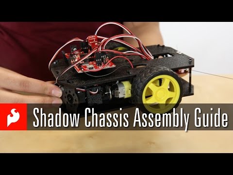
Our robot uses a combination of two Shadow Robot chassis to create a 4-wheeled robot. To connect the two frames, we used a mix of zip-ties and tape across overlapping areas of the base.
The four DC hub motors receive power outputs from the TB6612FNG Motor Driver H-Bridge circuit connected to the raspberry pi. There are two PWM outputs coming from the pi, one of those output signals controls two motors on the left side of the vehicle while the other PWM signal controls two motors on the right side of the vehicle. The two 7.4 V LiPo cells are connected in series to provide approximately 15.2 V to the motors. This configuration allows for efficient movement and turning. Here is the link with pin description for the Sparkfun Motor Driver. We followed those descriptions and connected the standby pin to a 3.3V pin from the Pi to make the driver functional. If the standby pin is not connected to a 3.3 V source, the robot will not move.
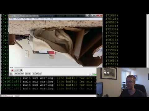
To aid the setting up of the Raspberry Pi camera stream, we used the below webpage, directly from the RPi website, to configure the camera. This page along with the embedded video will guide you in streaming the video from one computer to another.
This is the link for the instruction to set up the raspberry pi camera, and below is a YouTube video showing how to set up and run the Pi camera.
In order to create an efficient system for data transfer over WiFi, we set up a client-server socket communication. Since the IMU library is written in Python, we set up one side of the communication using Python. We set up the client side with Python and the server side with C++. The client can be written in C++ and server in Python. There was no reason for our choice. The client code reads angle data from the IMU and calculates a two PWM signal: one for the left side and another for the right side of the robot wheels. These signals are sent over WiFi to the server. The server parses through the data it receives for the PWM values. It then passes these PWM signals to the designated pins. The client and the server code can be found here: Client Server Code and Robot Code.
In order to set up the IMU with the Raspberry Pi Zero, we used the following webpage for guidance. BNO055 IMU wiring. You only need to follow the wiring instruction found on the page. When you get to the instruction to disable the kernel serial port, come to the instruction below.
- run
sudo raspi-configon a terminal - go to interfaces and serial
- click
nofor the first prompt andyesfor the second and reboot the Pi
For both sides of the Raspberry Pi, log in to the Pis and download the GitHub repository at Adafruit_Python_BNO055.
For the server side, first, compile the C++ code in the server folder. Using terminal go to the directory of the server folder and run the executable file using the command sudo ./[NAME OF THE EXECUTABLE FILE]. It will jump to the second line and stop. It will not do anything until it connects to the client.
On the client side, go to the directory of the client code and run the code using sudo python client.py. It will start displaying angle values and confirmation messages received from the server. You can tilt the IMU forward and backward to move the robot forward and backward respectively. Tilting to the right and the left will turn the robot likewise.
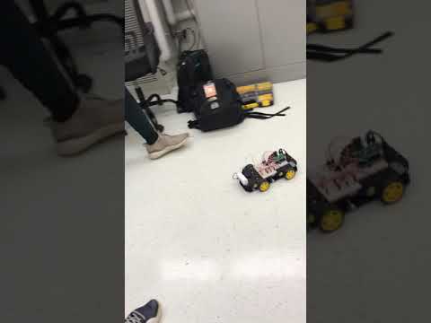
Below is a YouTube video showing the final robot demo.