Official Skyminer Wiring

The following is a list of pictures that showcase the wiring of the official Skyminer. Each section entails the related pages of the assembly manual and can be used to verify your progress in the assembly.
The safety precautions of the assembly manual must be followed at all times! You can find these safety precautions in the Safety Precautions sections of this page as well.
There are two versions available of the assembly manual:
Please refer to the following articles for the software & network configuration:
In case you need a video to showcase the respective assembly check please click here.
You can contact the team by:
It’s important that you assemble and operate this product and all components in strict accordance with the instructions in this manual.
Exercise extreme caution while handling printed circuit boards (PCBs) to avoid mechanical or electrical damage. Only handle the PCBs by the edges, to mini-mize the risk of electrostatic discharge damage.
Before connecting the power cord, ensure that you switch to the correct input range on the power supply unit that corresponds to the voltage that your electrical outlet provides.
Before powering up the Skywire Miner, ensure that all connections are secure for all components, and confirm that there are no loose screws or loose components anywhere within the Skywire Miner unit. Do not connect any devices to the Skywire Miner that are not included in this package.
Take time to consider situations that may be dangerous or cause damage:
- During operation, do not expose Skywire Miner to water or moisture.
- Do not expose Skywire Miner to heat from any source. This appliance is designed for reliable operation at normal ambient room temperatures.
- Do not tug in the middle of the power supply cable to unplug the unit. Unplug the Skywire Miner from the end of the cable, where the plug inserts into the socket.
- Place Skywire Miner where the power cord has adequate slack to safely connect the Skywire Miner to the power supply socket.
- Place the power cord in such a way that people cannot step on it. Do not place anything over the power cord.
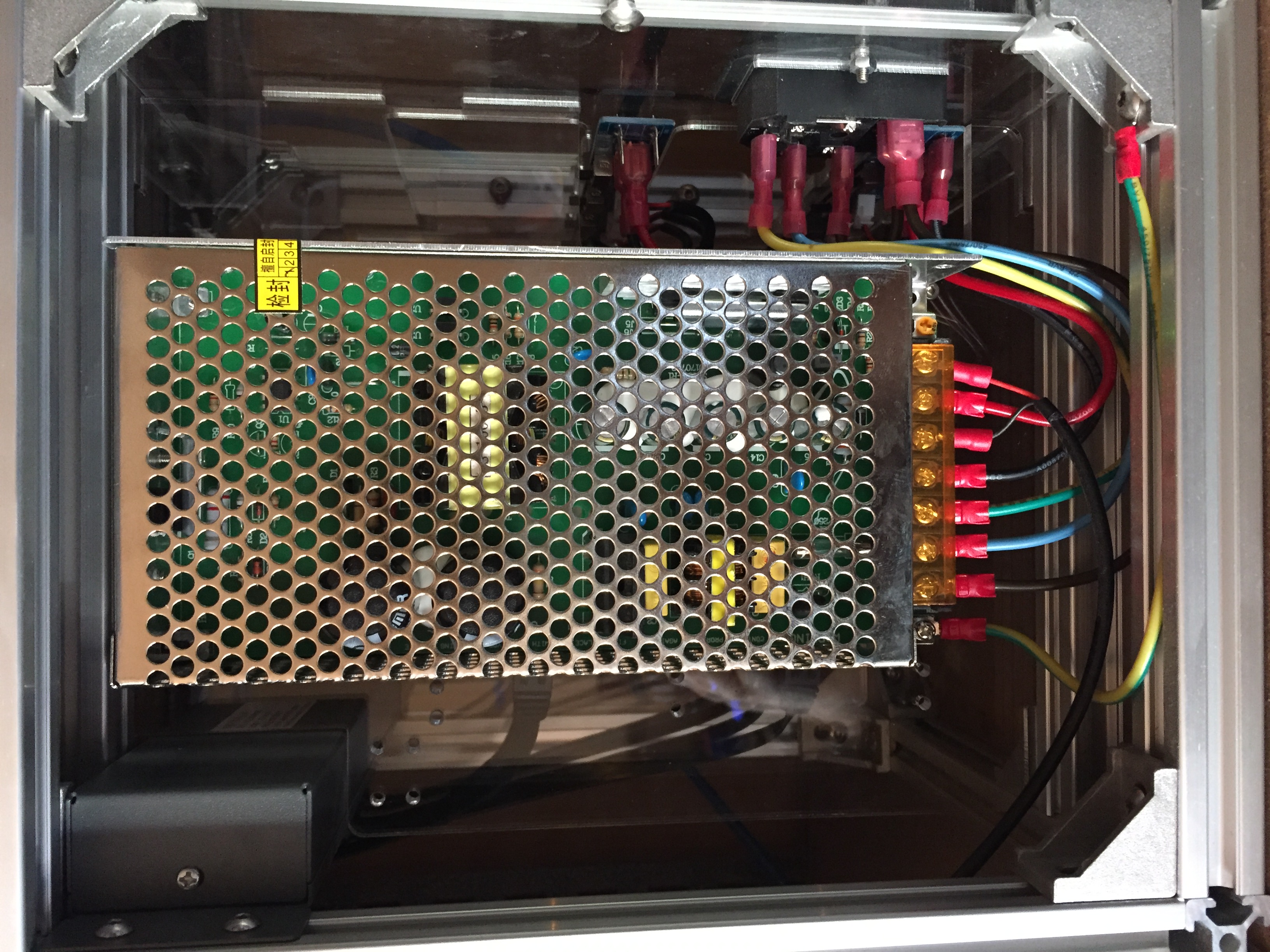
The power switching unit is also being called as 'PSU'.
- Page 27 in the assembly manual PDF (Page 28 search function)
- Page 27 in the assembly manual PDF (Page 28 search function)
- Page 17 in the assembly manual PDF (Page 18 search function)
In case one or multiple orange pi prime boards do not turn on & appear to be DOA (dead on arrival), it's often times useful to double-check the output voltage of the PSU. This process requires a multimeter or voltmeter. The following instructions are written & have been tested on a multimeter.
The output voltage of the PSU is expected to be ~5.0 V. In some cases, individual orange pi prime boards require a higher voltage than that before working properly (maximum 5.3 V).
In addition to the general safety precautions, please make sure to:
- remember to not operate on live equipment, ever!
- disconnect the power cords of the orange pi prime boards
- disconnect the power cord of the Skyminer router
Adjusting the PSU requires a multimeter:
- please follow the safety instructions provided by the producer of your multimeter
- attach the black measuring line to COM on your multimeter
- attach the red measuring line to mAVΩ on your multimeter
- set the multimeter to DC and the range to 20 V
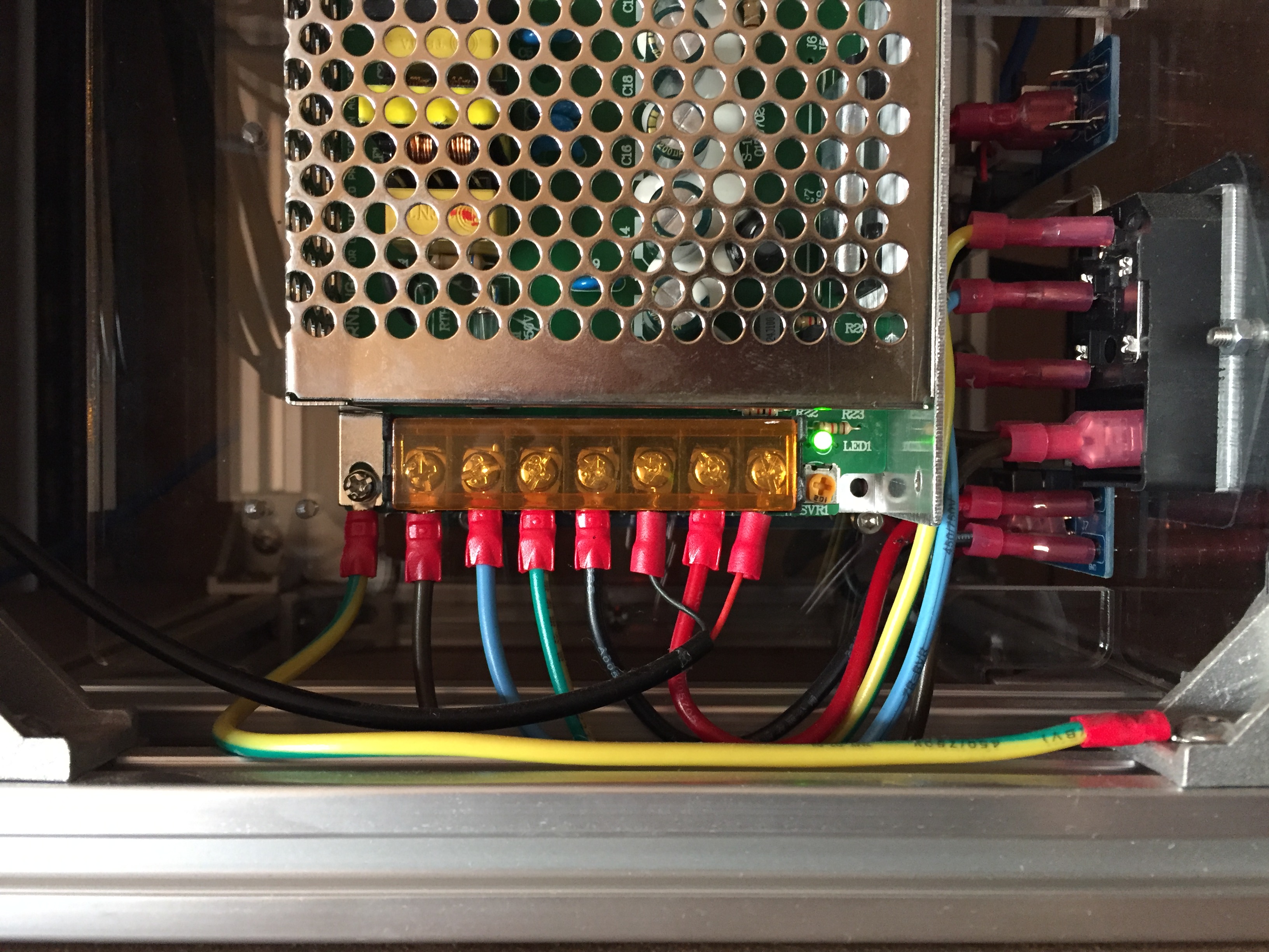
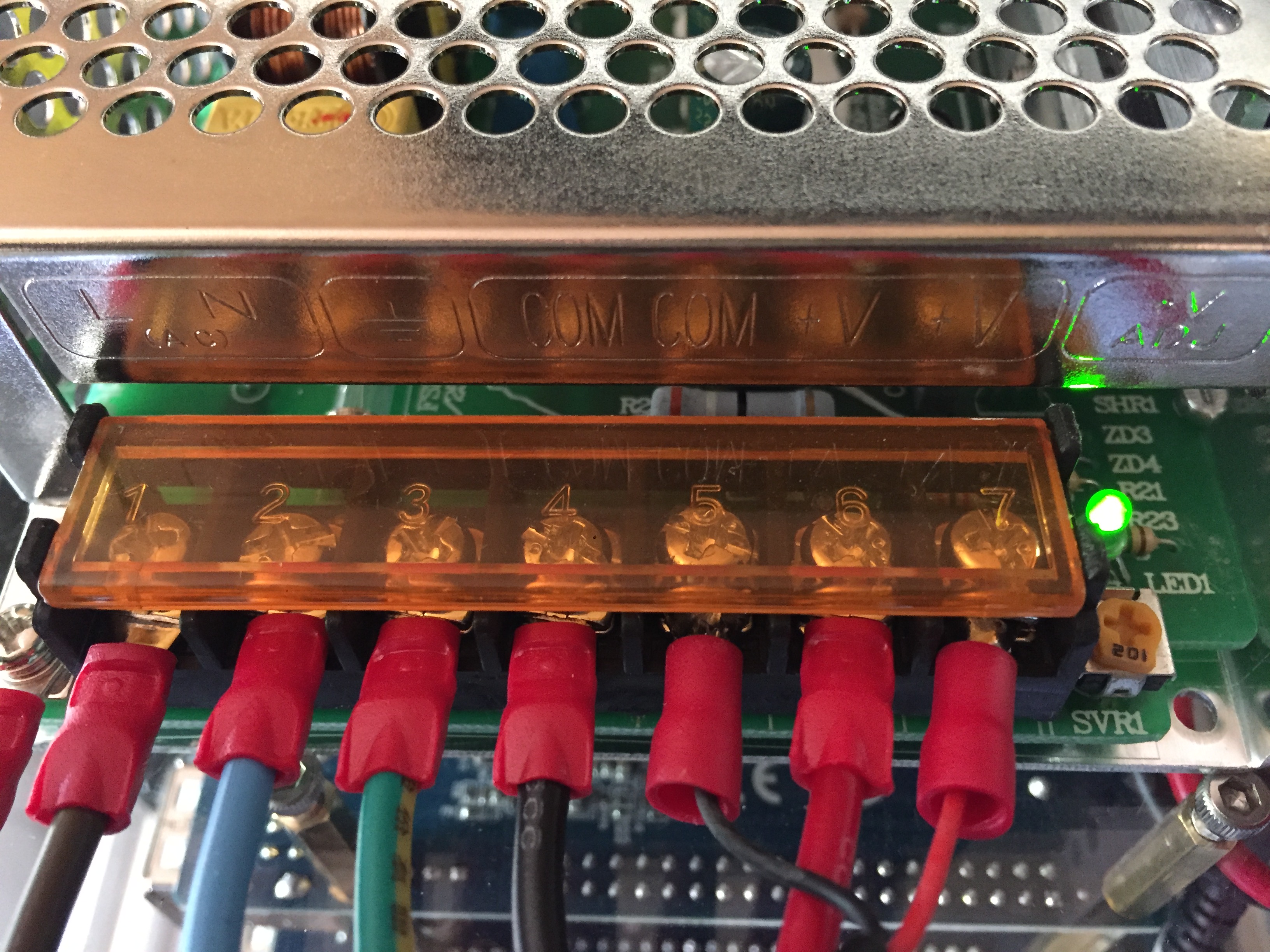
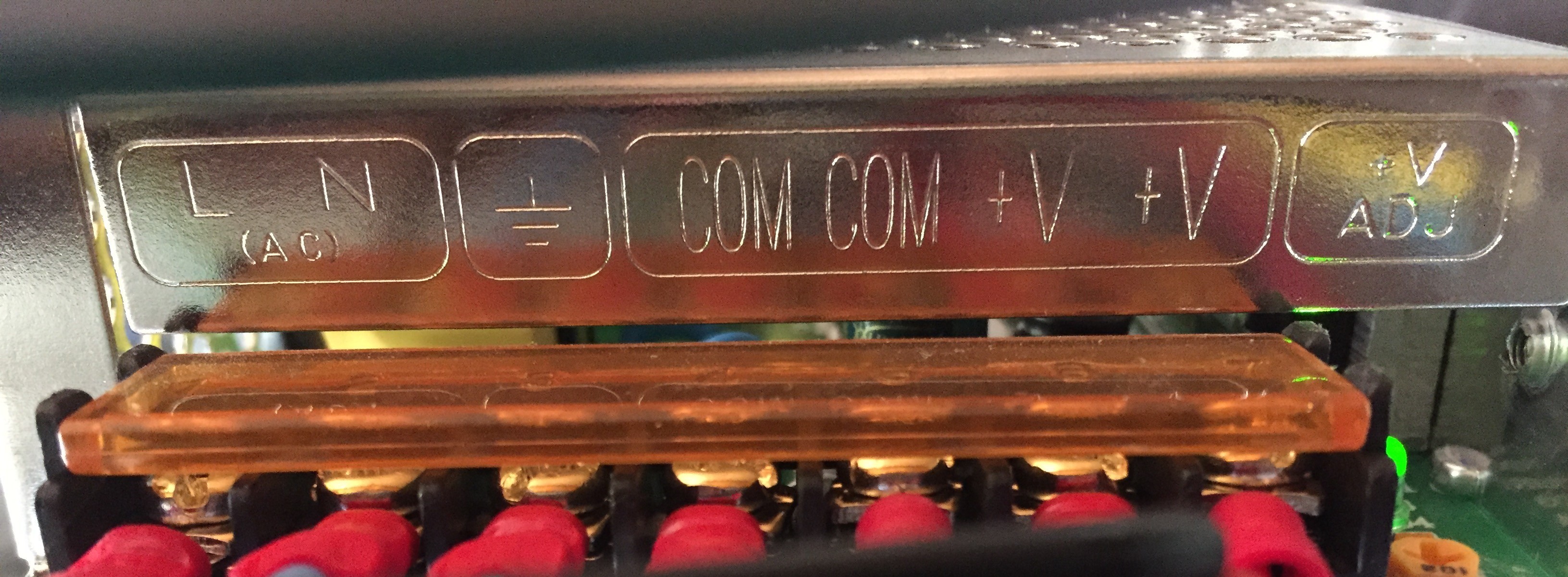
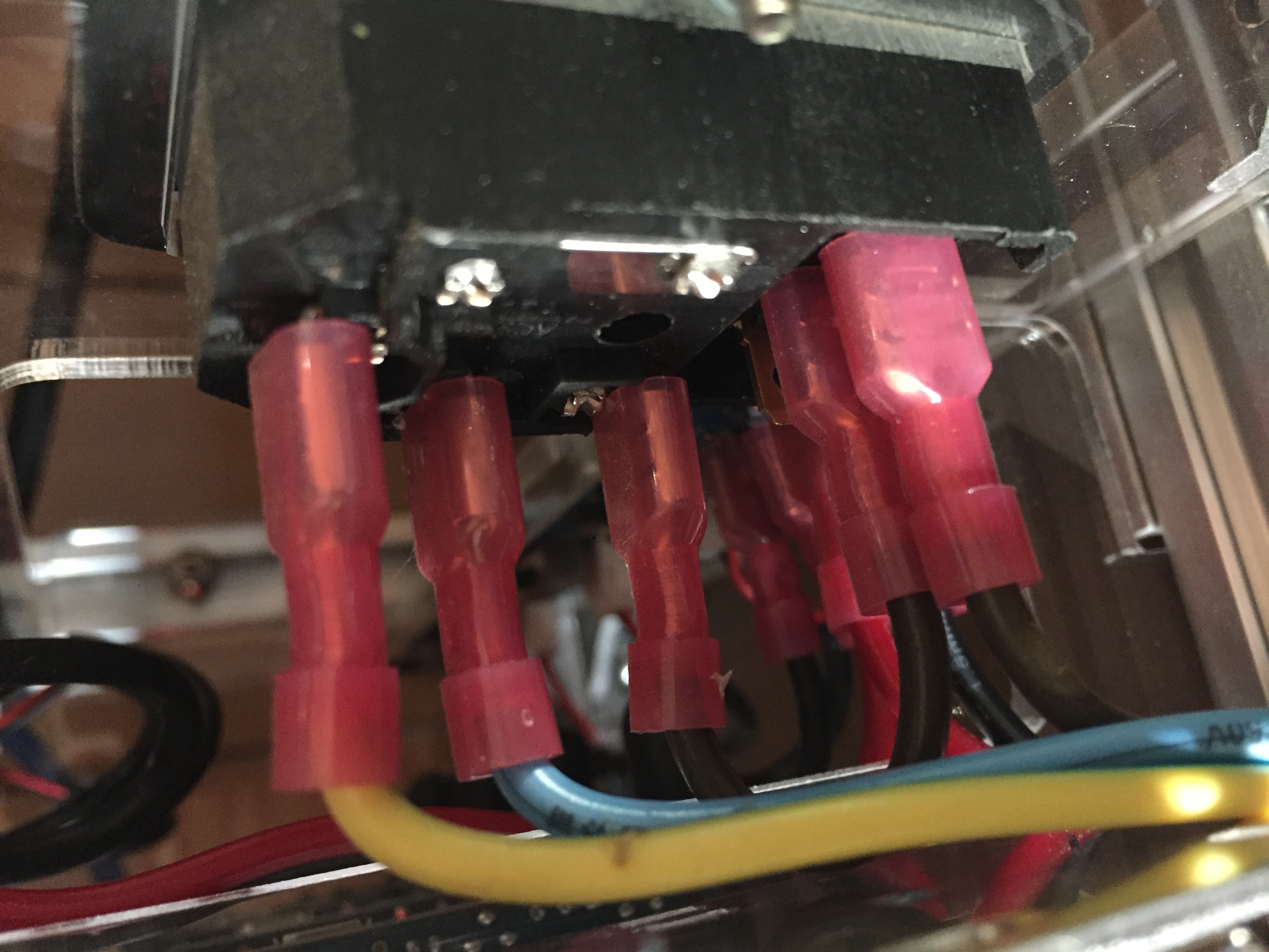
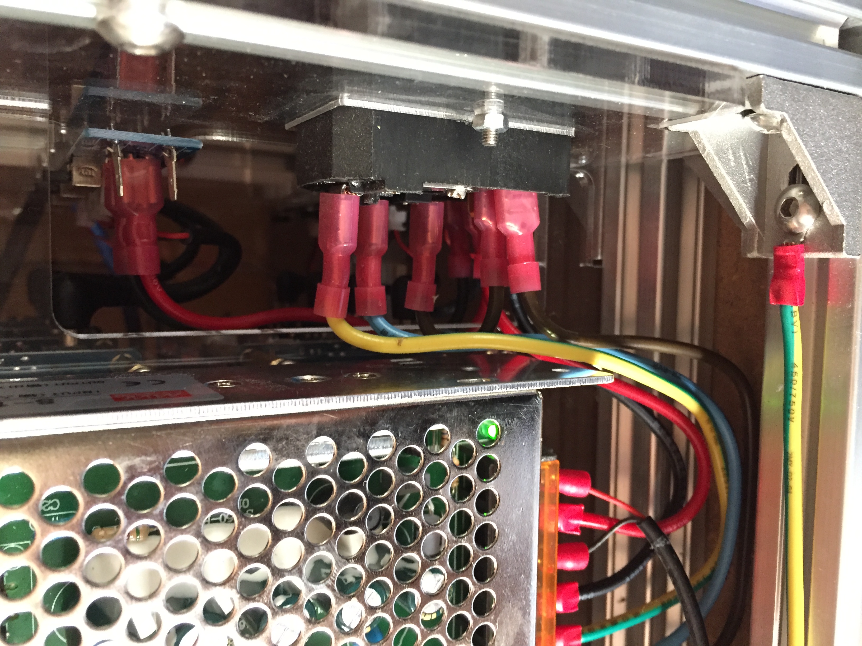
The terminal bar on the PSU can be used to measure the output voltage as well as to adjust the output voltage via adjustment screw. Note that adjusting the output voltage using the adjustment screw should never be done when the system is energized!
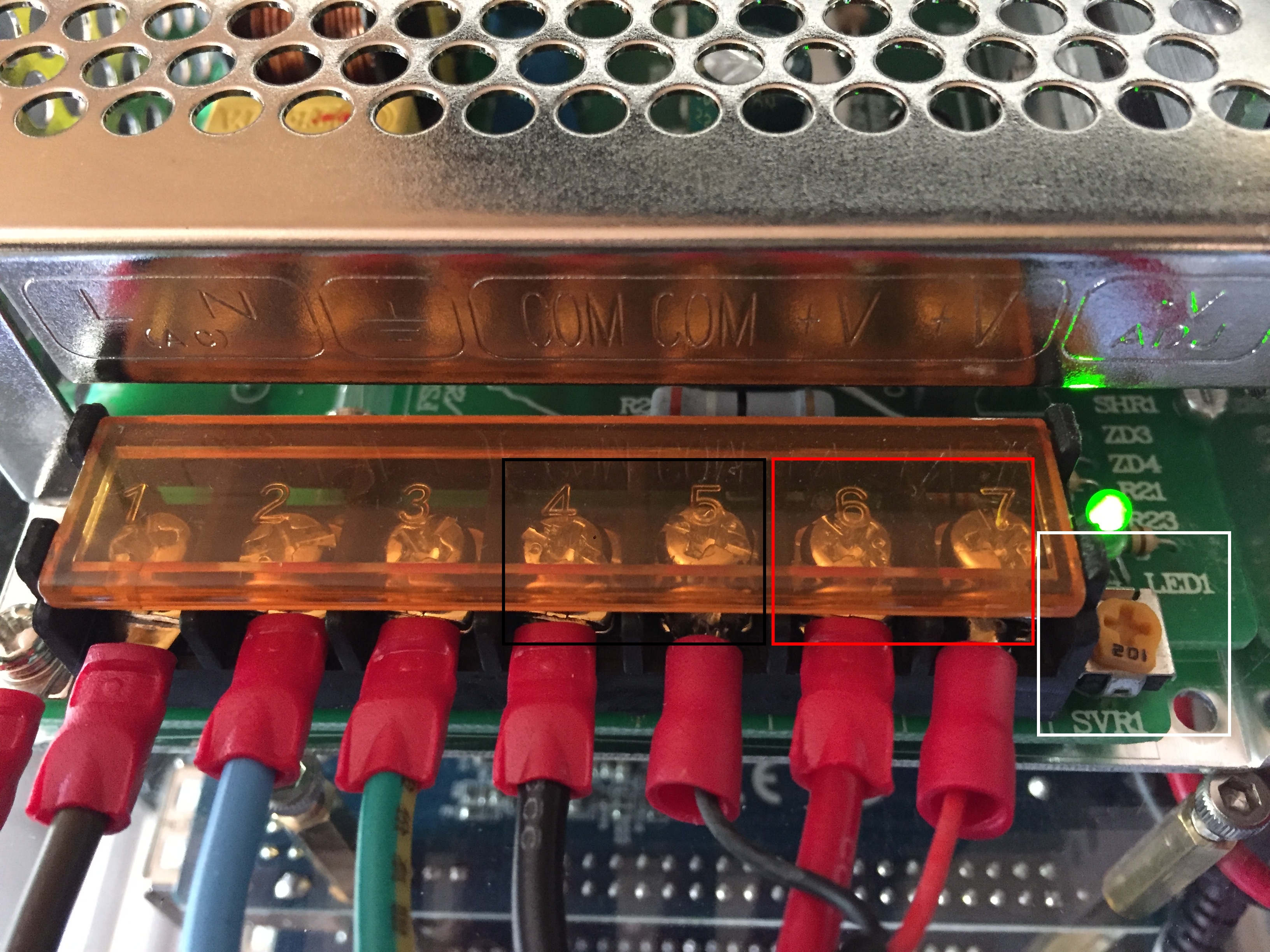
Measuring the output voltage on the PSU terminal bar can be done by:
- connecting the black measuring line to one of the COM screws (black rectangle)
- connecting the red measuring line to one of the V+ screws (red rectangle)
You can change the output voltage with the mentioned adjustment screw. Please disconnect the power cord first before proceeding. Turn the adjustment screw (white rectangle) and check the resulting voltage change with the multimeter. Please make sure to not exceed 5.3 V
Once the new output voltage has been set you can reconnect the power cords of the orange pi primes & the Skyminer router. If the board(s) still do not turn on even after adjusting the output voltage, the board(s) are confirmed to be DOA. Official Skyminer owners can request replacements from support via the support ticket form..