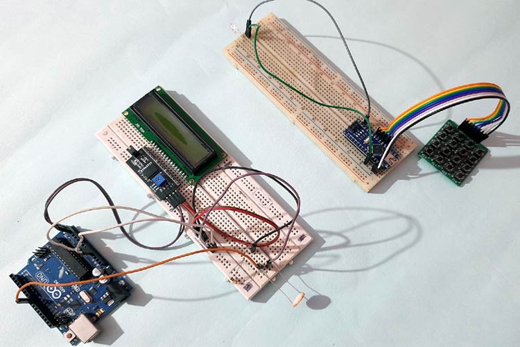
This project demonstrates Li-Fi (Light Fidelity) communication between two Arduino boards using visible light for data transmission. Text data is transmitted using an LED and a 4x4 keypad on the transmitter side and decoded on the receiver side using an LDR (Light Dependent Resistor). Li-Fi communication can be up to 100 times faster than traditional Wi-Fi.
- Features
- Components Required
- What is Li-Fi?
- Circuit Diagram
- Pin Configuration
- Installation
- Code Explanation
- How It Works
- Usage Instructions
- Troubleshooting
- Future Enhancements
- Wireless data transmission using visible light
- 16 different character transmission (0-9, *, #, A-D)
- Real-time text communication between two Arduino boards
- LCD displayfor received data visualisation
- Simple keypad interface for input
- No radio frequency interference
- Arduino UNO/Nano (1x)
- 4x4 Matrix Keypad (1x)
- 5mm LED (1x)
- 220Ω Resistor (1x)
- Breadboard
- Connecting Jumper Wires
- Arduino UNO (1x)
- LDR Sensor (1x)
- 10kΩ Resistor (1x)
- 16x2 Alphanumeric LCD Display (1x)
- I2C Interface Module for LCD (1x)
- Breadboard
- Connecting Jumper Wires
Li-Fi (Light Fidelity) is an advanced wireless communication technology that uses visible light for data transmission instead of radio waves. Key advantages include:
- High Speed: Can be up to 100 times faster than Wi-Fi
- Security: Light cannot pass through walls, providing inherent security
- No Radio Interference: Safe for use in sensitive environments
- Energy Efficient: Can use existing LED lighting infrastructure
The technology works by modulating light pulses at extremely high speeds (invisible to the human eye) to encode data, which is then decoded by light-sensitive receivers like photodiodes or LDRs.
Keypad Connection:
- Rows: A5, A4, A3, A2
- Columns: A1, A0, 12, 11
LED Connection:
- LED Anode → Pin 8 (through 220Ω resistor)
- LED Cathode → GND
LDR Connection:
- LDR Pin 1 → 5V
- LDR Pin 2 → Pin 8 (Analog Input) and 10kΩ resistor to GND
I2C LCD Connection:
- SDA → A4
- SCL → A5
- VCC → 5V
- GND → GND
| Component | Arduino Pin |
|---|---|
| Keypad R1 | A5 |
| Keypad R2 | A4 |
| Keypad R3 | A3 |
| Keypad R4 | A2 |
| Keypad C1 | A1 |
| Keypad C2 | A0 |
| Keypad C3 | 12 |
| Keypad C4 | 11 |
| LED (+) | 8 |
| Component | Arduino Pin |
|---|---|
| LDR Signal | 8 |
| LCD SDA | A4 |
| LCD SCL | A5 |
- Open Arduino IDE
- Go to Sketch → Include Library → Manage Libraries
- Search for "Keypad" and install the Keypad library by Mark Stanley and Alexander Brevig
- Or download from: Arduino Keypad Library
- Install Wire.h (Usually pre-installed with Arduino IDE)
- Install LiquidCrystal_I2C.h library:
- Go to Sketch → Include Library → Manage Libraries
- Search for "LiquidCrystal I2C" and install
- Connect the 4x4 keypad to Arduino Nano/UNO as per pin configuration
- Connect LED to pin 8 through a 220Ω current-limiting resistor
- Ensure proper power connections (5V and GND)
- Connect LDR in series with 10kΩ resistor (voltage divider circuit)
- Connect the junction point to Arduino pin 8
- Connect I2C LCD module (SDA to A4, SCL to A5)
- Power the LCD and Arduino properly
- Open transmitter code in Arduino IDE
- Select correct board and COM port
- Upload to transmitter Arduino
- Repeat for receiver Arduino with receiver code
The transmitter code uses unique pulse durations for each key:
- Key '1': 10ms HIGH pulse
- Key '2': 20ms HIGH pulse
- Key '3': 30ms HIGH pulse
- ... and so on up to Key 'D': 160ms HIGH pulse
When a key is pressed, the Arduino sends a HIGH pulse to the LED for a specific duration, followed by LOW state.
The receiver continuously monitors the LDR using the pulseIn() function to measure the duration of received light pulses. Based on the pulse duration, it identifies which key was pressed and displays it on the LCD.
Pulse duration ranges:
- 10,000-17,000 µs → Key '1'
- 20,000-27,000 µs → Key '2'
- And so on...
- User presses a key on the 4x4 keypad
- Arduino reads the keypress
- Arduino generates a unique HIGH pulse duration on pin 8
- LED emits light pulses corresponding to the data
- Light travels through air to the receiver
- LDR detects the light pulses from transmitter LED
- LDR converts light intensity changes to voltage variations
- Arduino measures the pulse duration using
pulseIn()function - Arduino decodes the pulse duration to identify the character
- Character is displayed on the 16x2 LCD
- Power On: Connect both Arduino boards to power supply
- Wait for Initialization: Receiver LCD will show "WELCOME TO CIRCUIT DIGEST"
- Position LEDs: Place the transmitter LED and receiver LDR facing each other at a distance of 5-30 cm
- Avoid Ambient Light: For best results, minimize ambient light interference
- Press Keys: Press any key on the transmitter keypad
- View Output: The corresponding character will appear on the receiver LCD as "Received: X"
- Keep the LED and LDR aligned properly
- Use in a moderately dark environment
- Maintain appropriate distance (not too close, not too far)
- Ensure stable power supply to both circuits
- Check I2C address (try 0x27 or 0x3F)
- Verify LCD connections (SDA, SCL, VCC, GND)
- Test LCD separately with I2C scanner sketch
- Adjust pulse duration ranges in receiver code
- Check ambient light conditions
- Verify LDR and resistor values
- Use Serial Monitor to debug pulse durations
- Check LED brightness and LDR sensitivity
- Reduce distance between transmitter and receiver
- Shield from external light sources
- Ensure stable power supply
- Verify keypad connections to Arduino pins
- Test keypad separately
- Check if Keypad library is properly installed
- Increased Data Rate: Implement faster modulation techniques
- Bidirectional Communication: Add reverse channel for acknowledgments
- Error Detection: Implement CRC or checksum for data integrity
- Multiple Channels: Use different colored LEDs for parallel communication
- Extended Range: Use high-power LEDs and photodiodes instead of LDR
- Full Text Messages: Store and transmit complete sentences
- Audio Transmission: Extend to voice or audio data transfer
- Internet Integration: Connect to IoT platforms for remote monitoring
The transmitter code initialises the keypad, reads key presses, and sends unique pulse patterns through the LED.
The receiver code uses the pulseIn() function to measure light pulse duration and decode the transmitted data.
Both complete code files are available in the project repository.
- Project Source: Circuit Digest
- Tutorial Link: Li-Fi Communication between Two Arduino
- ArduinoArduino Projects
This project is for educational purposes. Please refer to the original tutorial for licensing information.
For questions and discussions, visit the Circuit Digest Forum
Happy Making! 🔦✨