Repository navigation
gpio
GPIO (general-purpose input/output) is a pin the program uses directly: it sets the level of an output and reads the level of an input.
Every pin belongs to a port, GPIOA, GPIOB and on, and has a number from 0 to 15, so PA5 is pin 5 of port A.
One GPIO_t holds one pin: where it is and how it works.
Programs on OpenCPLC controllers use DIN and DOUT, built on GPIO, while drivers and bare-metal projects use GPIO directly.
-
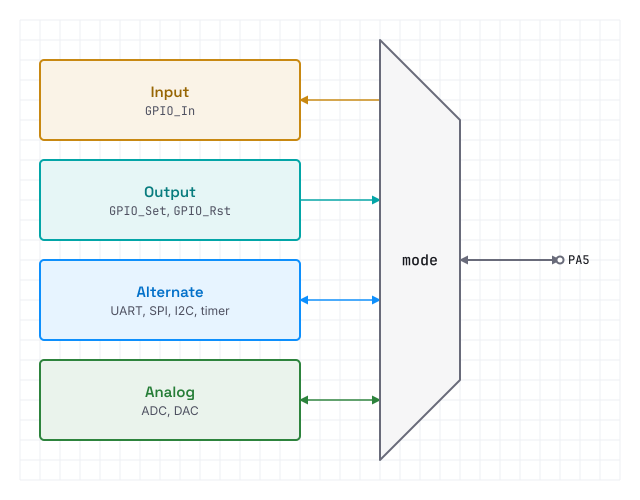
alternatepicks the peripheral by its number in the alternate function table of the datasheet. Drivers of UART, SPI and I2C set their pins from a pin map,GPIO_Map_t, so a program rarely needs to. - In analog mode the digital input and output are off, so nothing disturbs the ADC or the DAC on the pin.
- A pin can change its mode while running: the 1-Wire driver pulls its line low as an output, then reads it as an input.
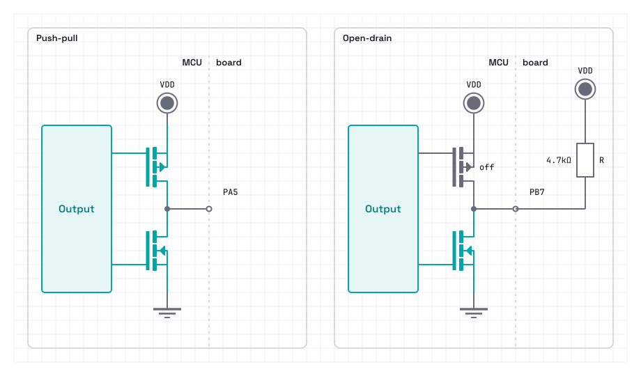
- Push-pull drives both levels: the upper transistor connects the pin to VDD, the lower one to GND.
- Open-drain only pulls the line low, and a resistor pulls it high. Many outputs can share one line, as on I2C, and any of them can pull it low.
-
speedsets how steep the edges are: low for a LED or a relay, since steep edges radiate interference, high for SPI or PWM.
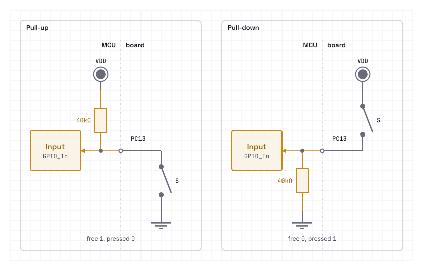
An input nothing drives is floating: it picks up interference and reads at random.
pull ties it weakly to VDD or to GND, so a free input reads 1 with GPIO_Pull_Up and 0 with GPIO_Pull_Down.
The internal resistor is weak, so a long cable or strong interference in the machine needs a stronger one on the board.
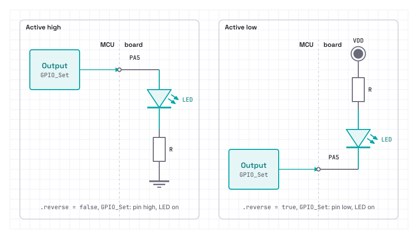
reverse turns the logic over: GPIO_Set drives the pin low, and GPIO_In reads a low pin as true.
So the code says what a level means, on, pressed, selected, and the wiring stays in the declaration of the pin.
A button to GND, a LED from VDD or an active-low chip select takes .reverse = true.
EXTI_t handles a rising or a falling edge at once, without waiting for the next pass of the loop.
-
rise_detectandfall_detectpick the edges,RiseHandlerandFallHandlerwhat runs on each. - A handler runs in the interrupt, so it should stay short: set a flag or count.
-
EXTI_Rise,EXTI_FallandEXTI_Eventsreturn the edges since the last read and clear the count, so pulses are counted with no handler at all. - One interrupt line serves pin
nof every port, soPA3andPB3cannot both have one.
Fields left out are zero: input, no pull, push-pull, the lowest speed, set off.
// A LED from PA5 to GND, a button from PC13 to GND
static GPIO_t led = { .port = GPIOA, .pin = 5, .mode = GPIO_Mode_Output };
static GPIO_t button = { .port = GPIOC, .pin = 13, .pull = GPIO_Pull_Up,
  .reverse = true };

// Pulses of a meter on PB3, an open collector to GND, counted on the falling edge
static EXTI_t meter = { .port = GPIOB, .pin = 3, .pull = GPIO_Pull_Up,
.fall_detect = true, .irq_enable = true };GPIO_Init writes the configuration to the port and drives the level set holds, so a pin starts as declared.
static uint32_t pulses; // of the meter since the start

void loop(void)
{
  GPIO_InitList(&led, &button, NULL);
  EXTI_Init(&meter);
  while(1) {
    // A pressed button pulls the pin low, and `reverse` reads it as true
    if(GPIO_In(&button)) GPIO_Set(&led);
    else GPIO_Rst(&led);
    pulses += EXTI_Fall(&meter); // the edges since the last pass
    let();
  }
}