Repository navigation
Figures
The book has 225 figures. Every one is specified by a <!-- FIGURE ... --> marker at the point it belongs in its chapter and drawn by a Python script, figures/scripts/chNN.py, from the same numbers the text uses (numpy, scipy, matplotlib; circuits, flowcharts and timing diagrams with schemdraw). The full plan, with what each figure shows, is FIGURES.md.
pip install -r requirements.txt
python scripts/build-figures.py          # all chapters
python scripts/build-figures.py ch07     # one chapter
node scripts/insert-figures.mjs          # place newly drawn figures below their markers
npm run figures:plan                     # rebuild FIGURES.md
CI runs every figure script on each push.
| Kind | Count |
|---|---|
| plot | 133 |
| block-diagram | 44 |
| timing-diagram | 10 |
| circuit | 9 |
| flowchart | 8 |
| waveform | 5 |
| schematic | 5 |
| state-diagram | 4 |
| wiring-diagram | 2 |
| kinematic-diagram | 2 |
| layout | 2 |
| table-graphic | 1 |
| Ch. | Title | Figures |
|---|---|---|
| 1 | From Requirement to Working System | 6 |
| 2 | System Architecture | 6 |
| 3 | Modeling and Simulation Workflow | 6 |
| 4 | Prototyping and Verification | 5 |
| 5 | Engineering Documentation | 5 |
| 6 | Sensors and Transducers | 5 |
| 7 | Measurement and Signal Conditioning | 6 |
| 8 | Data Acquisition Systems | 6 |
| 9 | Instrumentation Projects | 6 |
| 10 | Embedded-System Integration | 6 |
| 11 | IoT Systems | 6 |
| 12 | Edge Computing and Embedded AI | 6 |
| 13 | Robotics Fundamentals | 5 |
| 14 | Mobile Robotics | 5 |
| 15 | Robot Electronics and Control | 6 |
| 16 | Drones and Aerial Robotics | 6 |
| 17 | Robotic System Integration | 6 |
| 18 | Industrial Control Architecture | 5 |
| 19 | Industrial Sensors and Actuators | 5 |
| 20 | Industrial Motor Control | 5 |
| 21 | Industrial Communication and Safety | 5 |
| 22 | Solar PV System Design | 6 |
| 23 | Battery Energy Systems | 6 |
| 24 | Electric Vehicles | 6 |
| 25 | Microgrids and Hybrid Energy Systems | 6 |
| 26 | Communication-System Integration | 6 |
| 27 | Practical Signal Processing | 6 |
| 28 | Biomedical Instrumentation | 6 |
| 29 | Engineering Software Workflows | 5 |
| 30 | Scientific and Engineering Computing | 6 |
| 31 | Engineering Software Architecture | 5 |
| 32 | AI and Machine Learning for EEE | 6 |
| 33 | Engineering Simulation and Digital Twins | 6 |
| 34 | Project: Autonomous Line-Following Robot | 6 |
| 35 | Project: Smart Energy Monitor | 6 |
| 36 | Project: Solar Battery System | 5 |
| 37 | Project: Closed-Loop Motor Drive | 6 |
| 38 | Project: Wireless Sensor Network | 5 |
| 39 | Project: Engineering Simulation Tool | 5 |
| 40 | Capstone Engineering Project | 5 |
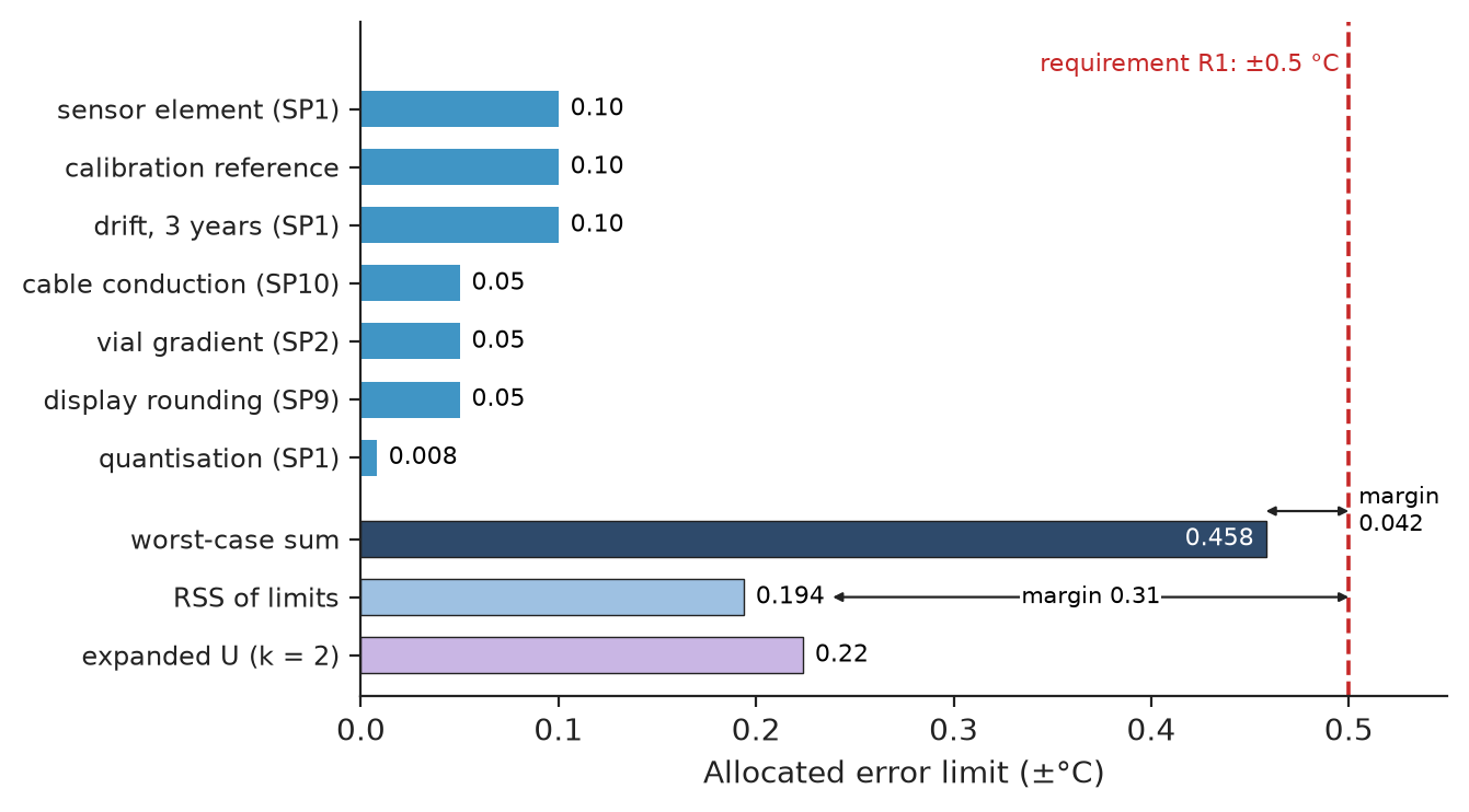
Allocated error budget for R1: contributions, worst-case sum and root-sum-square against the requirement.
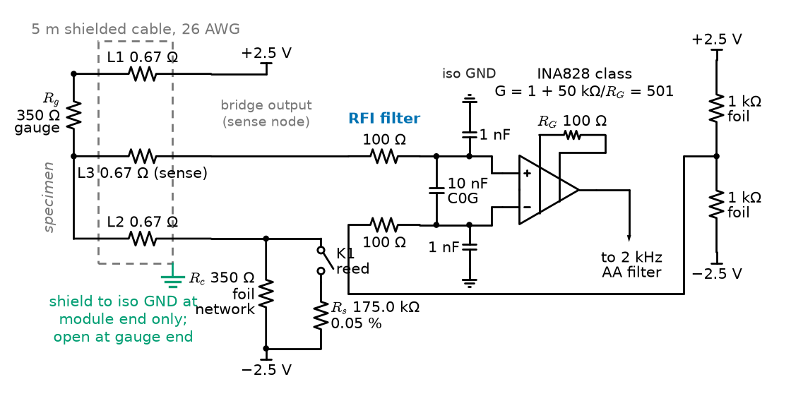
One channel of the quarter-bridge front end with 3-wire gauge connection, symmetric excitation, shunt calibration and RFI filter.
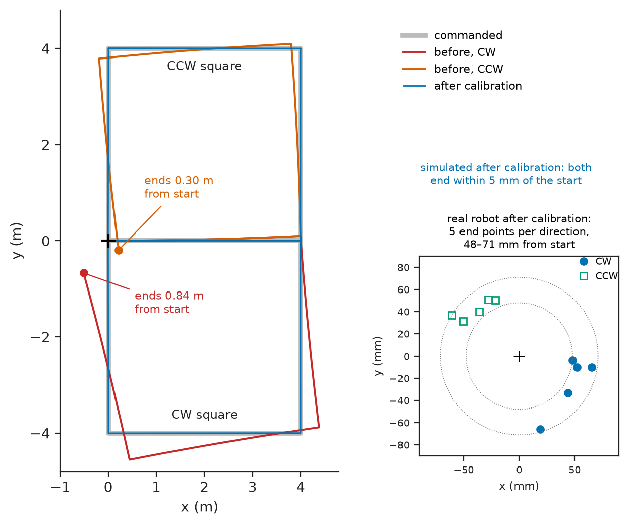
Bidirectional 4 m square test: true paths of the robot before and after odometry calibration.
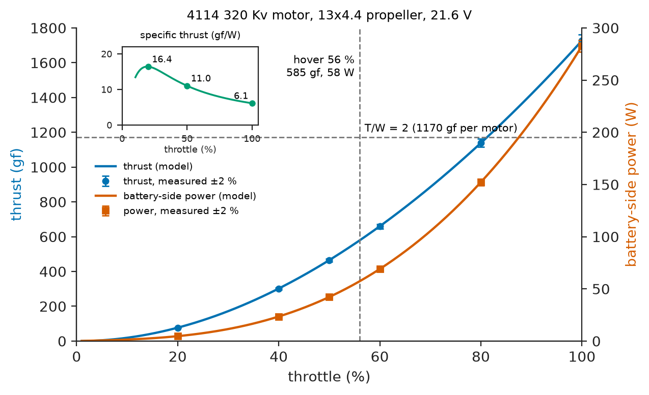
Thrust-stand characterisation of one 4114 320 Kv motor with 13x4.4 propeller at 21.6 V.
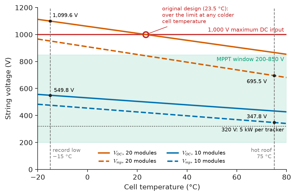
String voltage against cell temperature for 10- and 20-module strings inside the inverter's voltage window.
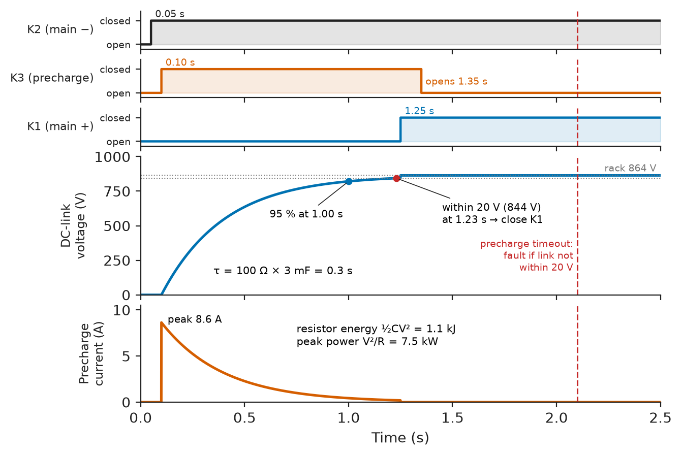
Contactor and precharge sequence when the cabinet connects to the PCS DC link.
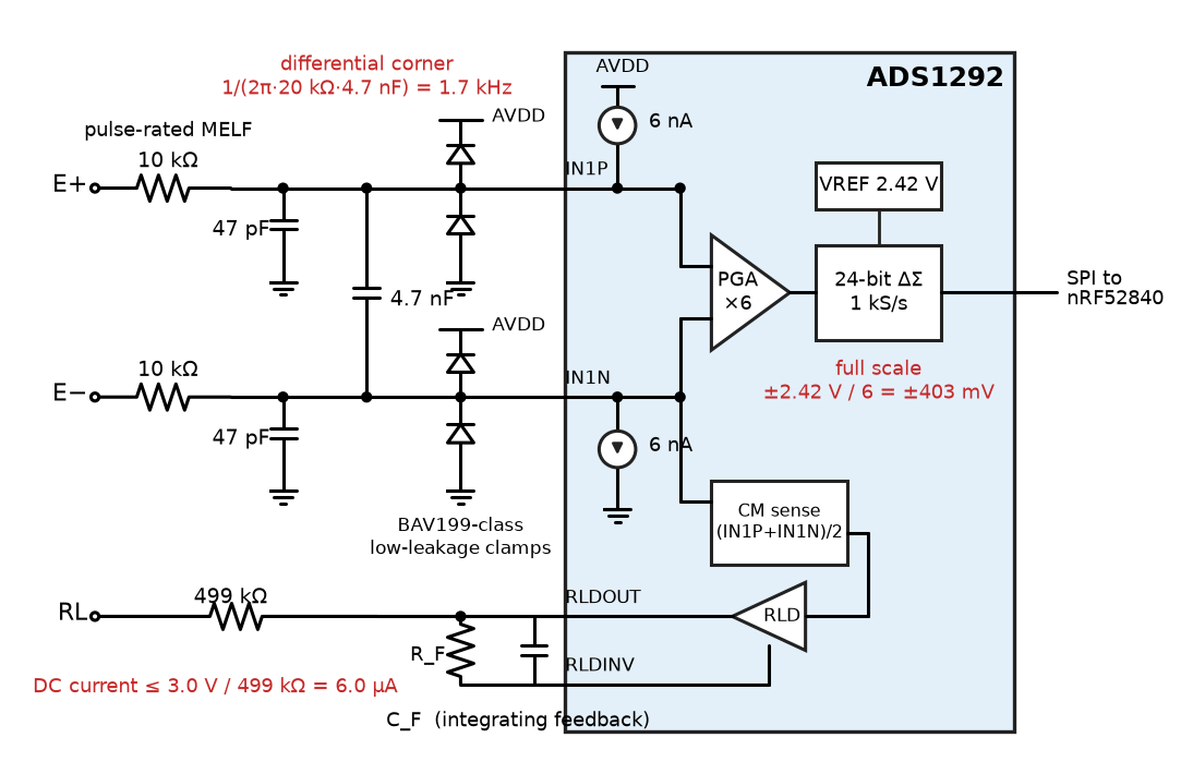
One lead pair of the ECG front end with protection, RFI filtering, lead-off detection and the right-leg driver.
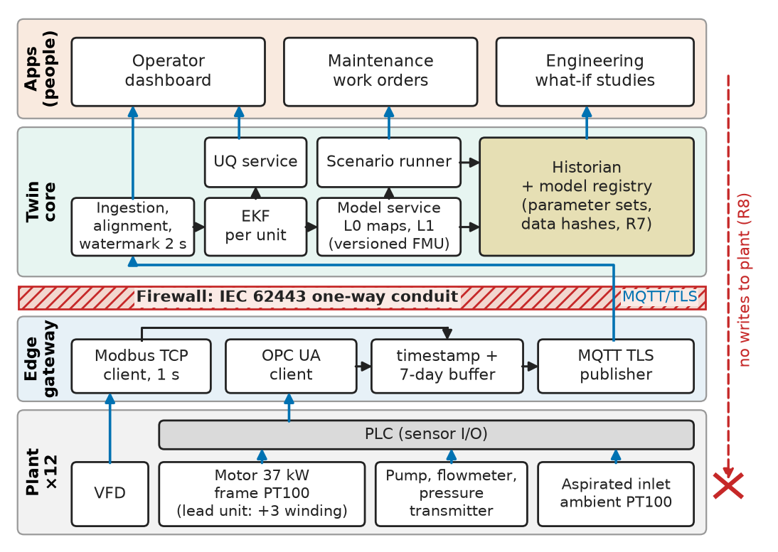
Architecture of the pump-set digital shadow from plant sensors to applications.
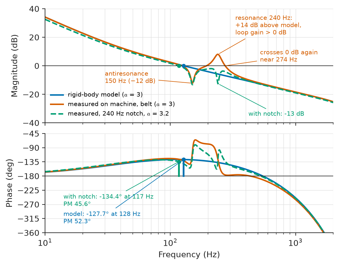
Open-loop frequency response of the speed loop on the machine, rigid model against measured, with and without the notch filter.