Nrf52 qspi flash #1188
Nrf52 qspi flash #1188
Conversation
- also move usb_init() from board_init() to port_init(0
qspi flash is still corrupted occasionally
- move write caching to flash_api for both internal and qspi flash
- fix flash write blocks for qspi
|
the super slow write speed really need some improvement !! I will try to implement
|

|
Write speed isn't critical to using CircuitPython. Yes, it'd be nice if it was faster but let's ignore it for now and focus on getting all of the APIs going. I suggest filing a separate issue for it for the full 4.0.0 release milestone and moving onto other tasks for now. |
|
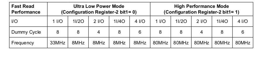
@tannewt phew, I am trying to increase usb msc buffer size to 8KB but it doesn't help as well. probably need to dive deeper into the flash datasheet timing etc ... I will try to wrap it up now. Update: just check datasheet of the flash on pca10056, we may need to enable high performance mode, will give it a try later. |
|
@hathach We'd like to make this implementation be as similar as possible to the atmel-samd QSPI and external flash implementation, so that we can factor out the common code as much as possible and only implement the lowest level routines in a chip-specific way. For instance, that code has parameterized chip support, and it already has caching logic. Did you try copying that impl? This impl is more different than we thought it would be. |
|
@dhalbert many of the spi std command for flash is handled by nrfx qspi driver. Since nrf52840 has enough memory (4K) to cache the whole page. I just refactor both caching for internal + external flash leaving it to only basic hal erase, read, program. At anywhere you could use block API flash_read_blocks/flash_write_blocks instead of internal/external_flash_write_blocks. The flash_ will use either internal or external depending on the config. Those can be changed to function pointer for concurrent internal + external uses if needed. |
|
There is additional logic in the atmel-samd port that isn't in this one because it wasn't started from a copy. For example, the SPI flash chip is detected rather than hard coded. Ideally this logic would be shared but for now it can be copied if that's easier. Ideally you'd only need to replace the implementations here but it hasn't been tested yet. |
|
@tannewt ah yeah, I am adding support device lookup table with JEDEC ID. Instead of using 3 bytes response from 0x9F for manufacture id, memory type and capacity, can we use only 2 bytes response from 0x90 command (manufacture id, device id) ? |
…f flash device is not one of supported.

change nrf qspi to blocking model
Rename config pin name from QSPI_FLASH_ --> MICROPY_QSPI_
|
I tried to enable high performance bit but couldn't get it written any faster. It is probably default mode already. Note: nrf52 SCK clock speed is only up to 32 Mhz. I post an issue on Nordic devzone to see if there is anyone got more lucky than us. |
|
Nordic testing is a bit higher than us for write speed (different tool can be a bit different), but seem like write speed will be somewhat 1/10 of read speed. We may not improve it much with pca10056.
|
|
@hathach can you resolve the conflicts that have arisen? Thanks. |
|
@dhalbert I am making more improvement while porting this for Arduino, I will clean up and update the flash code then resolve the conflict for this a bit later. |
|
@hathach I stumbled on this while looking at the datasheet for something else. It says to use high drive strength to drive the QSPI pins: [page 267, section 6.19.1]
|
| #define MICROPY_QSPI_DATA2 NRF_GPIO_PIN_MAP(0, 12) | ||
| #define MICROPY_QSPI_DATA3 NRF_GPIO_PIN_MAP(0, 14) | ||
| #define MICROPY_QSPI_SCK NRF_GPIO_PIN_MAP(0, 8) | ||
| #define MICROPY_QSPI_CS NRF_GPIO_PIN_MAP(1, 8) |
There was a problem hiding this comment.
Seems inconsistent that all other defines in this file use the pin__ objects but for QSPI we use the pin number
| nrf_gpio_cfg_input(11, NRF_GPIO_PIN_PULLUP); | ||
| nrf_gpio_cfg_input(12, NRF_GPIO_PIN_PULLUP); | ||
| nrf_gpio_cfg_input(24, NRF_GPIO_PIN_PULLUP); | ||
| nrf_gpio_cfg_input(25, NRF_GPIO_PIN_PULLUP); |
There was a problem hiding this comment.
This looks like test code that shouldn't be merged.
|
|
||
|
|
||
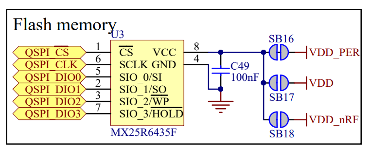
| // Settings for the Gigadevice GD25Q16C 2MiB SPI flash. | ||
| // Datasheet: http://www.gigadevice.com/wp-content/uploads/2017/12/DS-00086-GD25Q16C-Rev2.6.pdf |
There was a problem hiding this comment.
This link returns 404 for me
| .status_quad_enable = (1 << 9)\ | ||
| } | ||
|
|
||
| #define MX25R6435F {\ |
There was a problem hiding this comment.
Add a datasheet link as well?
|
I'm trying to get this patch working on my board. I use a different flash chip but I added it to The CDC is properly detected and works just fine, but it also doesn't seem to be aware of the flash storage: Also, the chip i use is 128Mbit/16Mbyte and I specified it as so |
|
@arturo182 What chip is it, and does it truly have 16MiB (binary megabytes), or is it smaller? Also 16MB is just at the boundary between FAT12 and FAT16, and it's possible either Linux or FatFS is confused about just where that boundary is: one might be think it's FAT12 and the other might think it's FAT16. |
|
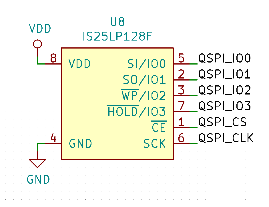
Ah yes, I should've written the model, it's IS25LP128F, datasheet available here: http://www.issi.com/WW/pdf/25LP-WP128F.pdf |
|
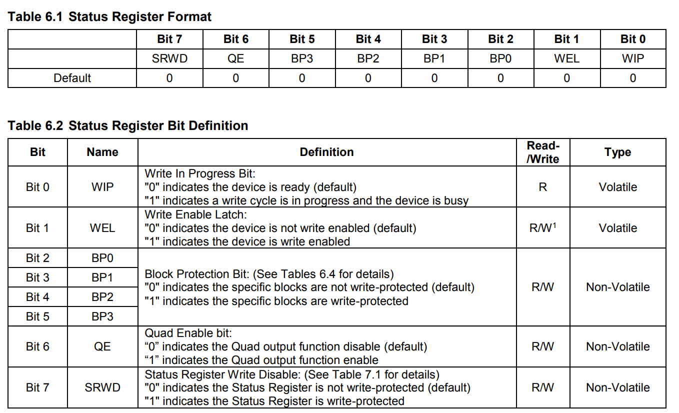
@aturo182 is the flash wired for quad mode ? If yes, Also please check the status registers mask in device config to make sure it is correct value to put flash device into quad mode. |
|
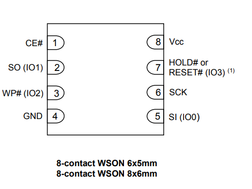
I use As for the design, I'm not sure what more is needed for quad mode wiring, I pretty much copied the PCA10056 except with a different chip, most qspi flash ICs seem to be pin compatible. Datasheet: My design: @ladyada do you think it would be possible to post the nrf52840 feather schematic part with the QSPI flash so I could compare? |
|
@arturo182 I think most of the QSPI testing has been done on the Nordic dev boards. The feather exists but I'm not sure if anyone has tested it at all. |
|
I see, I thought @hathach was using some early nRF52840 feather prototypes to test the qspi :D Looking at the PCA10056 schematic the pinout seems the same, I don't think there is any limit to which pins can be used as QSPI, so maybe I'll double check my soldering, but seems odd that it managed so read the chip id without a problem. |
|
@arturo182 I only tested with pca10056, maybe you should start there to see if that works for you first and then moving to your custom board. |
|
Good idea, I'll try that :D |
|
I tested the code on PCA10056 and it works there so must be something with either the soldering, the chip or my gpio choice. |
|
FYI I'm moving the atmel-samd port to tiny usb and factoring out all of the usb stuff from the ports. This includes MSC so I plan on factoring out the spi flash chip support as well. I'll add support for QSPI on nRF based on this PR (thanks for it!) but will not merge it directly. Expect to see a PR for it next week sometime. Thanks! |
It is still work in progress but current code works with 8 MB MX25R6435F on pca10056. The read speed is ok, but the write is painfully slow (will improve later). I would like to have as many review/suggestion as possible.
flash_apidirectory and move all the flash there#1049