Fluid Spindle Setup
FluidNC supports multiple spindles on one machine. Spindles can be controlled by different hardware interfaces like relays, PWM, DACs, or RS485 serial interfaces to VFDs. Lasers are treated as spindles.
Each spindle is assigned a range of tool numbers. You change spindles by issuing the GCode command "M6 Tn", where n is the tool number. Tool numbers within the assigned range for a given spindle will activate that spindle - and the detailed number within the range could be used to select the specific tool on the spindle. This lets you have, for example, a single machine with an ATC spindle and a laser. A single GCode file could allow you to etch and cutout a part. Most CAM programs support tool numbers. You could also have a gantry with both a low-speed high-torque pulley spindle and also a high-speed direct drive spindle.

0-10V control is designed for spindle controllers that have a 0-10V control input. The signal out of FluidNC is PWM at the pin voltage (typically 3.3v). You must use an adapter to scale it to the voltage you need (typically 10V). The reason for this special case of PWM control is that the VFDs typically have a separate signal input for forward and reverse directions. If you don't need direction control, you should use the basic PWM spindle type.
-
- Type: Pin
- Range: gpio or i2so
- Default: NO_PIN
- Details: This is used to signal forward rotation if you have separate pins for forward and reverse.
-
- Type: Pin
- Range: gpio or i2so
- Default: NO_PIN
- Details: This is used to signal reverse rotation if you have separate pins for forward and reverse.
-
- Type: Integer
- Range: 1 to 20000000
- Default: 5000
- Details: This is the frequency of the PWM signal. The precision (number of bits) of the the PWM signal is based on the frequency. 20000000 will give you only 4 bits of precision. Each time you divide the pwm_freq by 2, you get another bit of precision.
-
- Type: Pin
- Range: gpio
- Default: NO_PIN
- Details: This is the pin that the output PWM signal is put on. It turn off with M5. The s0_with_disable value can effect this pin.
-
- Type: Pin
- Range: gpio or i2so
- Default: NO_PIN
- Details: This pin can be used as an enable pin. The disable_with_s0 value can effect this pin.
-
- Type: Pin
- Range: gpio or i2so
- Default: NO_PIN
- Details:
-
- Type: Boolean
- Default: false
- Details: By default disable is controlled by M5. If you also want it to disable when speed is set to 0 (S0), set this to true.
-
- Type: Boolean
- Default: true
- Details: By default the speed signal is controlled by the speed value. It will stay on even in M5 mode. If you want it to go to the S0 value with M5, set this to true.
-
- Type: Integer
- Range: 0 to 20000 (milliseconds)
- Default: 0
- Details: This is the time that will given for the spindle to spin up to maximum RPM as defined in the speed map. The gcode following the speed change will will wait until the spin up has completed. The time is proportional the RPM change. If the change in RPM is only half of the full scale, the delay will only be half of the spinup_ms value.
-
- Type: Pin
- Range: 0 to 255
- Default: 0
- Details: This sets the range of tool numbers for this spindle. If you have multiple spindles you should setup a range for both spindles. When you specify a tool number with the M6 Tnnn gcode command it will switch to the tool that covers that range. The max value is 255. See more here
- With 1 Spindle: It does not matter what the value is, but set it to 0.
- With Multiple Spindles: Set the first spindle to 0 and the other spindles at higher values. Each spindle should have a unique number. If you have a relay spindle with tool_num: 0 and a laser with tool_num: 100, all tool numbers from 0 to 100 will use the relay and all tool numbers from 100 to 255 will use the laser. Send M6T100 to use the laser.
-
- Type: Speed Map
- Details: This allows you to fine tune the speeds. You can linearize the RPM vs. PWM across the range and you can set things like minimum speeds. It is a very comprehensive feature that has its own page.
Example
10V:
  forward_pin: gpio.13
  reverse_pin: gpio.17
  pwm_hz: 5000
  output_pin: gpio.4
  enable_pin: NO_PIN
  direction_pin: NO_PIN
  disable_with_s0: false
  s0_with_disable: true
  spinup_ms: 0
  spindown_ms: 0
  tool_num: 0
  speed_map: 0=0.000% 1000=0.000% 24000=100.000%
The BESC spindle is designed for use with RC hobby type Brushless Electronic Speed Controllers. These use the same type of PWM signal as an RC servo. These typically only use one I/O pin, but other standard spindle pins can be used. The PWM signal ranges from a min value to a max value, so it is generally outputting at all times.
Special settings
- pwm_hz: Most BESC use a 50Hz frequency. Some can go a little higher, but rarely more than 200.
- min_pulse_us: This is the pulse length in microseconds used for spindle off. This can be used to fine tune the range.
- max_pwm_us: This is the pulse length in microseconds used for max speed.
besc:
  pwm_hz: 50
  output_pin: gpio.4
  enable_pin: NO_PIN
  direction_pin: NO_PIN
  disable_with_s0: false
  s0_with_disable: true
  spinup_ms: 0
  spindown_ms: 0
  tool_num: 100
  speed_map: 0=0.000% 255=100.000%
  min_pulse_us: 900
  max_pulse_us: 2200
Special Note This could be used to control a hobby servo in an application like a pen plotter. If you wanted to use M3S255 to move then pen up and an M5 to move it down. Also see the RC servo feature under motors.
The DAC uses the ESP32's build in DAC hardware. This can only be used on gpio.25 and gpio.26. It outputs a 0-3.3V analog voltage (not PWM). In most cases a PWM will be better. The DAC resolution is only 8bit (0-255) and a PWM can be up to 16bit (0-65535).
example
DAC:
  output_pin: gpio.25
  enable_pin: NO_PIN
  direction_pin: NO_PIN
  disable_with_s0: false
  s0_with_disable: true
  spinup_ms: 0
  spindown_ms: 0
  tool_num: 100
speed_map: 0=0.000% 255=100.000%These spindles are controlled via a RS485 connection. They are a little more complicated to setup, but they offer several advantages. They constantly monitor the spindle. If it appears the spindle is not working at the specified speed, the job will be stopped. It is important that the VFD is fully powered on before the the ESP32 is powered on. Some take several seconds before they are ready to communicate. Do not power cycle the VFD when the ESP32 is on. It may interrupt the communications and cause problems.
Note: Most VFD can also be controlled by a 0-10V signal.

This is the standard Huanyang VFD (all power levels). Part numbers start with Hy, like HY02D223B-T. The control is via RS485.
The VFD registers need to be setup prior to use. FluidNC will not change any of the registers. Read your VDF documentation on how to do that. Here are some typical values that work for most spindles.
| Register | Value | Description |
|---|---|---|
| PD001 | 2 | RS485 Control of run command |
| PD002 | 2 | RS485 Control of frequency |
| PD004 | 400 | Base frequency as rated on spindle |
| PD005 | 400 | Maximum frequency Hz (400Hz * 60sec/min = 24000rpm) |
| PD011 | 100 | Minimum speed in Hz (Typ. Air cooled 120, Water cooled 100) |
| PD014 | 6 | Acceleration time in seconds |
| PD015 | 6 | Deceleration time |
| PD023 | 1 | Enable reverse |
| PD141 | 220 | Spindle Voltage |
| PD142 | 3.7 | Max current (typ. 0.8kw=3.7) |
| PD143 | 2 | Poles |
| PD144 | 3000 | Revolutions at 50Hz |
| PD163 | 1 | RS485 Modbus address |
| PD164 | 1 | Baud rate of 9600 |
| PD165 | 3 | RS485 Mode RTU, 8N1 |
The min and max speeds set in the VFD will be displayed in the startup messages. They might be spread out through the messages, because they are coming from a separate task.
[MSG:INFO: VFD: Max speed:24000rpm]
[MSG:INFO: VFD: Min speed:6000rpm]
A minimum speed is typical with VFD spindles because they lack power and can overheat at lower speeds. A good speed linearization setting for the values above would be...
speed_map: 0=0% 0=25% 6000=25% 24000=100%The minimum speed of 6000 is 25% of the max speed of 24000. This setting would mean all values between 0-6000 would still result in 6000 RPM.
Check your RS485 adapter documentation for proper wiring methods and connections. Here is some information on the RS485 module.
Huanyang:
  uart:
    txd_pin: gpio.26
    rxd_pin: gpio.16
    rts_pin: gpio.4
    baud: 9600
    mode: 8N1
  modbus_id: 1
  tool_num: 0
  speed_map: 0=0% 0=25% 6000=25% 24000=100%
Important notes The VFD provides feedback to FluidNC. We use this to make sure the spindle is running at the right speed. If it is not running at the speed requested, it will shut down with an alarm after a few seconds. This could be due to many reasons. One reason is that the VFD has a max and min frequency setting. If you request a speed lower than the min it will run at the minimum. The same condition applies to the maximum. Therefore, if you request a speed above 0, but outside the range. The reported speed will not match your requested speed and will shut down. You will get a warning message at the serial console why this is happening. This issue can be fixed by using the correct type of speed_map.
YL620 is a Chinese VFD made by Yalang.

They can be controlled by 0-10V analog or by RS485 (Modbus). The following notes are for RS485 use.
The VFD registers need to be setup prior to use. FluidNC will not change any of the registers. Read your VDF documentation on how to do that. Here are some typical values that work for most spindles.
The Hz values given below indicate the frequency that is sent to the motor. A typical 2-pole motor will rotate once per Hz, so to get RPMs you multiply Hz (cycles/sec) times 60 (sec/min). So a 2-pole motor at 400Hz runs at 400 * 60 = 24,000 RPM nominally. In practice it will run slightly slower due a real-world factor called "slip". A 24,000 nominal motor might actually run at 23,500 with no load and 23,000 RPM under load.
| Register | Value | Description |
|---|---|---|
| P00.00 | 4000 | Main frequency in deci-HZ - 4000 is 400.0 Hz |
| P00.01 | 3 | Command Source. 3 is for control via RS485 |
| P03.00 | 3 | RS485 Baud Rate. 3 is for 9600 |
| P03.01 | 1 | Modbus Address. Typically you want to use 1. |
| P03.02 | 2 | RS485 Data format. 2 is 8 data bits, 1 stop bit, no parity |
| P03.08 | 1000 | Lowest frequency in deci-Hz - 1000 is 100.0Hz |
A minimum speed is typical with VFD spindles because they lack power and can overheat at lower speeds. A good speed linearization setting for the values above would be...
speed_map: 0=0% 0=25% 6000=25% 24000=100%The minimum speed of 6000 is 25% of the max speed of 24000. This setting would mean all values between 0-6000 would still result in 6000 RPM.
Check your RS485 adapter documentation for proper wiring methods and connections. Here is some information on the RS485 module.
YL620:
  uart:
    txd_pin: gpio.26
    rxd_pin: gpio.16
    rts_pin: gpio.4
    baud: 9600
    mode: 8N1
  modbus_id: 1
  tool_num: 0
  speed_map: 0=0% 0=25% 6000=25% 24000=100%
Important notes The VFD provides feedback to FluidNC. We use this to make sure the spindle is running at the right speed. If it is not running at the speed requested, it will shut down with an alarm after a few seconds. This could be due to many reasons. One reason is that the VFD has a max and min frequency setting. If you request a speed lower than the min it will run at the minimum. The same condition applies to the maximum. Therefore, if you request a speed above 0, but outside the range. The reported speed will not match your requested speed and will shut down. You will get a warning message at the serial console why this is happening. This issue can be fixed by using the correct type of speed_map.

This is the standard H100 VFD (all power levels). Part numbers typically look like H100-xxx.
The VFD registers need to be setup prior to use. FluidNC will not change any of the registers. Read your VDF documentation on how to do that.
The most relevant sections are:
F011 (min frequency) F005 (max frequency) The min and max speeds set in the VFD will be displayed in the startup messages. They might be spread out through the messages, because they are coming from a separate task.
[MSG:INFO: VFD: Max speed:24000rpm] [MSG:INFO: VFD: Min speed:6000rpm]
A minimum speed is typical with VFD spindles because they lack power and can overheat at lower speeds. For speed_map, feedback and the RS485 adapter settings, see the Huanyang section for more details.
If you don't specify the speed_map, the firmware will automatically put in the default values based on the frequencies that are set in the VFD. Only specify a speed_map if you use a gearbox or other contraption.

The Huanyang P2 series inverters, also dubbed 'H2A/H2B/H2C' or sometimes 'P2A' inverters are supported as well. This product was designed to be the 2nd generation of the popular Huanyang inverter from hy-electrical.com. These VFD's are small, and low power VFD's are usually white or gray. The sticker on the side of the inverter clearly tells that this is the inverter in question.
The manual can unfortunately be a bit confusing at times when it comes to setting up the RS485 connection.
At the top of the box is a RS485 connector with a 4-wire screw terminal. Wiring should use these 4 pin:
- GND = GND of Arduino
- A = RS+485
- B = RS-485
- VCC = 5V of Arduino
Prefer to use a shielded wire for the connector, and never run this wire next to a 220V, stepper or spindle wire. Also, ground one end of the shielding.
ALWAYS read the manual for VFD's! This is imperative to get motor speed etc. all correct. The H2x series inverters use real RPM values, so you need to set these accordingly, or the device won't work correctly. Next to that, you need to set certain settings to get RS485 working correctly, most notably:
| Setting | Value | Description |
|---|---|---|
| F0.02 | 7 | Set RS485 mode |
| F0.04 | 2 | Set RS485 mode |
| F0.09 | 4 | Set RS485 mode |
| F9.00 | 4 | 19200 baud |
| F9.01 | 0 | 8,N,1 parity |
| F9.02 | 1 | ModBus address |
| F9.05 | 0 | Non-standard modbus mode |
| F9.07 | 0 | Write operations responded |
We recommend setting 19200,8N1 for this VFD. During spindle sync, there can be quite a bit of communication, and 2400 baud might get you in trouble. 19200 is more than enough for anything you want to throw at a VFD. Using even higher baud rates will probably just result in errors.
Manufacturer: Shenzhen NowForever Electronics Technology CO.,LTD.
Website: http://www.nowforever.cn/
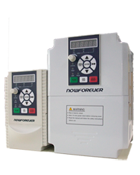
The D series of VFDs can be found in the control box of chinese CNC6040 cnc routers.
Unfortunately there is no manual for the D series so all of this information is based on the manual for the E series.
However there is a comparison chart made by someone else that shows that almost all parameters are the same.
The manual for the E series can be found online in various places by searching for nowforever e100 manual using your preferred search engine.
Comparison chart (german, also contains link for e series manual): http://moh-computer.de/frequenzumformer-parameter/
The current implementation for supporting NowForever VFDs has been tested against the D100S1R5B (D series, 1PH AC 220V 50/60hz input, 8A output) inverter.
It should work for other VFDs in the D series too as well as the E series since its manual has been used for reference of the parameters and protocol details.
If controlling the VFD through RS485 isn't working for some reason both the D and E series support a 0-10V interface as well.
This includes controlling the direction trough another input of the VFD. (See manual for details)
Here is a selection of the parameters needed to make the VFD (D and E series) communicate with FluidNC:
Selection of RS485 as control and frequency source:
| Register | Value | Description | Possible Values |
|---|---|---|---|
| P0-000 | 2 | Command source | 0: Keypad 1: Control inputs 2: RS485 |
| P0-001 | 0 | Frequency source | 0: main frequency source 1: auxiliary frequency source 2: main + aux 3: max(main, aux) 4: selectd by control input |
| P0-002 | 6 | Main frequency source selection | 0: Keypad Potentiometer 1: Keypad Up Down Arrow 2: AIN1 3: AIN2 4: Multistep speed 5: PID 6: RS485 7: Internal PLC |
RS485 parameters:
| Register | Value | Description | Possible Values |
|---|---|---|---|
| P0-055 | any free address between 1 and 31 | Address of VFD | 1- 31: slave addresses 2: master address |
| P0-056 | 2 works just fine | Baudrate | 0: 2400bps 1: 4800bps 2: 9600bps 3: 19200bps 4: 38400bps |
| P0-057 | 0 | Data framing | 0:1 start bit, 8 data bits, no parity, 1 stop bit 1: 1 start bit, 8 data bits, even parity, 1 stop bit 2: 1 start bit, 8 data bits, odd parity, 1 stop bit |
Setting min and max speed:
| Register | Value | Description | Possible Values |
|---|---|---|---|
| P0-007 | Whatever your spindle can handle | Max frequency | Min frequency - 600hz |
| P0-008 | Whatever your spindle can handle | Min frequency | 0 - Max frequency |
The following registers are read / written to by FluidNC:
Read access only:
| Register | Description |
|---|---|
| 0x007 | Max frequency in hz * 100, same as config parameter P0-007 |
| 0x008 | Min frequency in hz * 100, same as config parameter P0-008 |
| 0x300 | Current fault number 0 = no fault 1-18 = fault number |
| 0x500 | VFD status Bit 0: run, 1=run, 0=stop Bit 1: direction, 1=ccw, 0=cw Bit 2: control, 1=local, 0=remote Bit 3: sight fault, 1=fault, 0=no fault Bit 4: fault, 1=fault, 0=no fault Bit 5-15: reserved |
| 0x502 | Current output frequency in hz * 100 |
Write access only:
| Register | Description |
|---|---|
| 0x900 | VFD control Bit 0: run, 1=run, 0=stop Bit 1: direction, 1=ccw, 0=cw Bit 2: jog, 1=jog, 0=stop Bit 3: reset, 1=reset, 0=dont reset Bit 4-15: reserved |
| 0x901 | Speed to be set in hz * 100 |
Example YAML config:
NowForever:
  uart:
    txd_pin: gpio.17
    rxd_pin: gpio.4
    rts_pin: gpio.16
    baud: 9600
    mode: 8N1
  modbus_id: 1
  tool_num: 0
  speed_map: 0=0% 24000=100%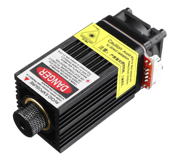
Laser is considered a spindle because gcode does not have laser specific codes. It uses the RPM value as a power level. Lasers also have special requirements.
-
They always operate like the advance laser mode of Grbl
- They will only operate during a G1, G2, or G3 move.
- They turn off when in idle or doing a rapid move.
- M3 is constant power and M4 is dynamic power mode (scales linearly with speed during accel/decel)
-
speed_map: final xxx=100% can be whatever you want, but it is typically 255 or 1000. This would need to be used in the CAM software as the max power number.
Laser:
  pwm_hz: 5000
  output_pin: gpio.4
  enable_pin: NO_PIN
  disable_with_s0: false
  s0_with_disable: true
  tool_num: 0
speed_map: 0=0.000% 255=100.000%This is automatically created if you did not specify a spindle in your config file.

This is like a PWM signal except that the pin will be full on for any speed above 0 that you select. PWM signals can quickly destroy a relay.
relay:
  direction_pin: NO_PIN
  output_pin: gpio.26
  enable_pin: NO_PIN
  disable_with_s0: false
  s0_with_disable: true
  spinup_ms: 0
  spindown_ms: 0
  tool_num: 0
speed_map: 0=0.000% 0=100.000% 1=100.000%The M4 (spindle reverse on) command will only be accepted if a direction pin is assigned to an I/O pin.

PWM:
  pwm_hz: 5000
  output_pin: gpio.2
  enable_pin: gpio.22
  direction_pin: NO_PIN
  disable_with_s0: false
  s0_with_disable: true
  spinup_ms: 0
  spindown_ms: 0
  tool_num: 0
speed_map: 0=0% 10000=100%You can define as many as your hardware will support. They will act totally independently. You must use separate I/O pins for each one. Simply add each spindle definition to the config file. Each must have a unique tool_num:
You switch between tools with the tool change gcode (M6). M6 T2 would switch to the spindle that covers tool number 2. If the spindles are offset, you will need to deal with that.
- The simplest way to to rezero the new spindle.
- You could use a separate coordinate system like G54 for one spindle and G55 for another.
- You could create a little macro that zeros the machine based on the known offset, like move to zero, move the offset amount and rezero.
- I get Error 20 Unsupported command for M4 M4 will only work on spindles that support reversing or lasers. If there is a direction pin for the spindle type you are using it must be assigned a pin