Stardate 20241101, The basic electronics work. #8
crunchysteve
announced in
News
Replies: 1 comment
-
|
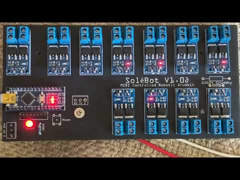
And further to testing the "MarkMothersboard" electronics controller for SoléBot, the board now runs HardwareTest.ino, as per this video... |
Beta Was this translation helpful? Give feedback.
0 replies
Sign up for free
to join this conversation on GitHub.
Already have an account?
Sign in to comment
Uh oh!
There was an error while loading. Please reload this page.
-
OK, after discovering a minor, easily fixable problem with the SoléBot motherboard (The MarkMothersboard, I'm so dining out on that pun, at the moment), in that I'd not connected all 3 data input pads for the MOSFET switch boards, nor all 3 ground pads, then only put 2 pins between the motherboard and the switch module, some of the channels weren't working. This was fixed with around 3 hours of very fiddly soldering of fine wires to bridge the gaps and now the electronics work, all the way from the Arduino to the solenoids. Pretty blinkenlicht uberwhere. Clearly I don't sprechen ze deutsch. My apologies, anglo/aussie humour and some slightly ADHD overexcitement. Here's the Nano running blink, which is the default load on a brand new board.
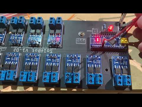
Because SoléBot uses pins D2 to D12, I had to jumper to the other pins to test, but it all works and there's no room on the workbench for my laptop, so I'll sort that next, after a few chores get done.
Initially, I'll be loading the hardware test code for now, effectively the C equivalent of a windup drumming monkey toy, four on the floor at 120 BPM. Testing the MIDI reader will come once the drum kit is outfited with the electromechanical beaters and a full, 24 volt and PWM test has been run. Currently the board only has serial in/out breakouts, as I'll be using a serial/MIDI shield board for development of the more real world approach.
Now, the minor board error - the 4 board free giveaway, genuinely free, I'll pay postage, is this crook board, so you'll need to put 6 header pins in for each mosfet switch input. That'll be easier than the fiddly, sweary lacing and soldering I had to do to fix it. The mosfet switches are also on an angle, too, as I've used the just sufficient pin protrusion on the power end screw headers to make a good connection with the mother board's power lines. If you can source the mosfet boards without the headers fitted, I'd suggest only fitting the output header, and using a pair of wire links between the motherboard and the switch module supply input.
The update to the Fritzing and Gerber files should happen in the next week or so, but my mother-in-law is entering the palliative stage of MND (AKA ALS in the US, although MND is the class, ALS is an instance), so life (and death) is affecting other plans frequently. If you want to contribute to this project financially, right now, donate to your regional MND or ALS charity, as I'm not comfortable with taking donations for this project at this very early stage, if ever. It's my hobby, not a job. Donations to MND/ALS, human rights charities or environmental causes fit my values, so, if they also fit yours, donate to those instead.
Cheers,
Crunchy.
Beta Was this translation helpful? Give feedback.
All reactions