The ESP8266 is a System on a Chip (SoC), manufactured by the Chinese company Espressif. It consists of a Tensilica L106 32-bit micro controller unit (MCU) and a Wi-Fi transceiver. It has 11 GPIO pins* (General Purpose Input/Output pins), and an analog input as well. This means that you can program it like any normal Arduino or other microcontroller. And on top of that, you get Wi-Fi communication, so you can use it to connect to your Wi-Fi network, connect to the Internet, host a web server with real web pages, let your smartphone connect to it.
there are different ways to program the ESP8266, but I'll only cover the method using the Arduino IDE. This is really easy for beginners, and it's a very familiar environment if you've used Arduino boards before. Just keep in mind that it's not limited to this option: there's also an official SDK available to program it in real C, this is very useful if you want to optimize your code or do some advanced tricks that aren't supported by the Arduino IDE. Another possibility is to flash it with a LUA interpreter, so you can upload and run LUA scripts.
- An ESP8266 board
- A computer that can run the Arduino IDE (Windows, Mac or Linux)
- A USB-to-Serial converter, it is very important that you use a 3.3V model
- A USB cable
- A 3.3V power supply or voltage regulator
- A Wi-Fi network
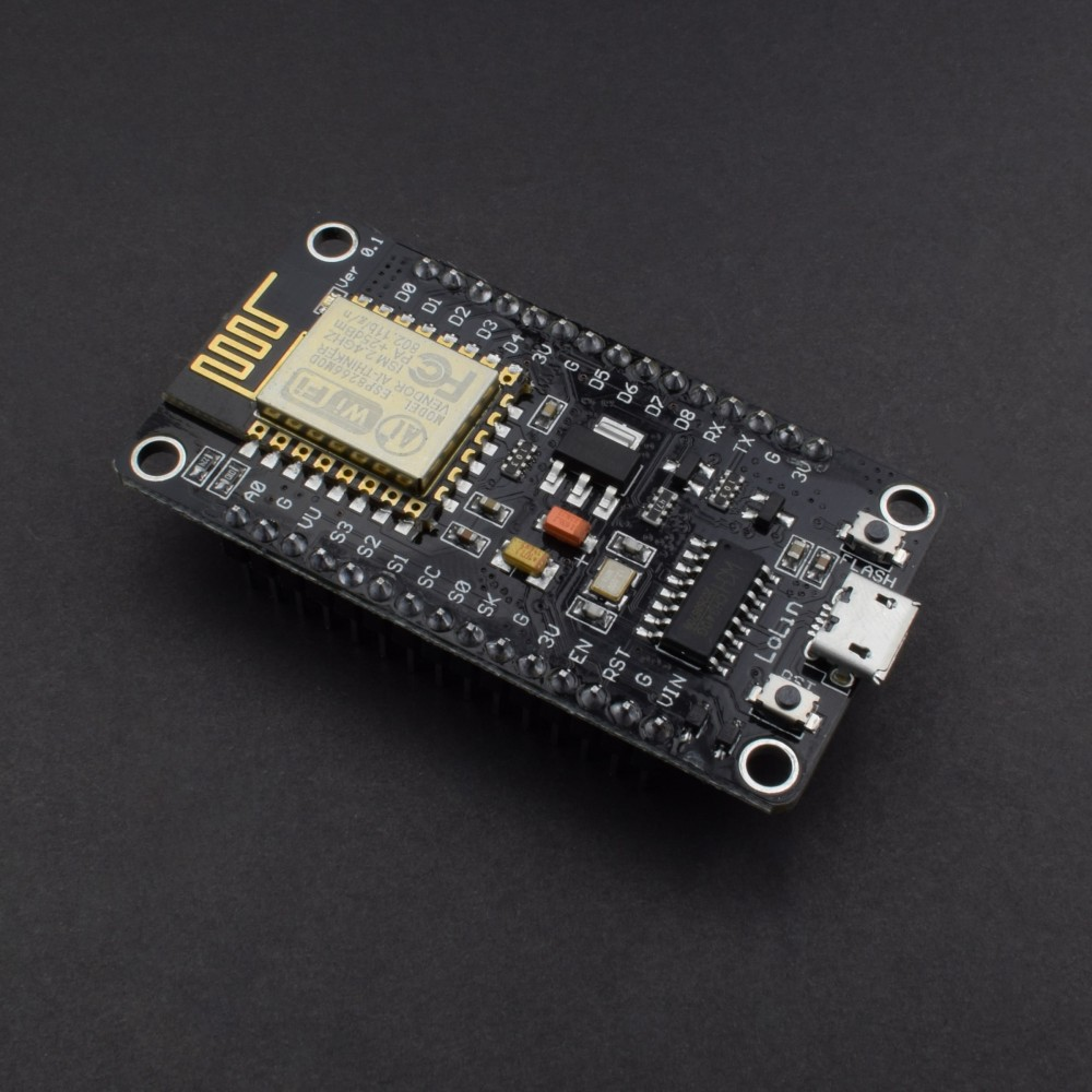
Some boards have all kinds of features on-board to help developing ESP8266 hardware and software: for example, a USB to Serial converter for programming, a 3.3V regulator for power, on-board LEDs for debugging, a voltage divider to scale the analog input etc.
If you want to add an ESP8266 to a small project, or if you want a cheaper* board, you might want to buy a board that doesn't have these features. In that case, you can buy one of the many ESP-## modules developed by AI Thinker. They contain just the ESP8266 and the necessary components to run it. To program the board, you'll need an external USB-to-Serial converter. With some modules, you get an on-board antenna (PCB or ceramic) and an LED, some boards have just an antenna connector, or no LEDs at all. They also differ in physical size, and flash memory size. An important thing to notice, is that some boards do not break out all GPIO pins. For example. the ESP-01 only has 2 I/O pins available (apart from the TX and RX pins), while other modules like the ESP-07 or ESP-12 break out all available I/O pins.
There are two main categories of ESP8266 boards: development boards with a USB interface (USB-to-Serial convertor) on-board, and boards without a USB connection.
- Connect the ground (GND) of the USB-to-Serial converter to the ground of the ESP8266.
- Connect the RX-pin of the USB-to-Serial converter to the TXD pin of the ESP8266. (On some boards, it's labelled TX instead of TXD, but it's the same pin.)
- Connect the TX-pin of the USB-to-Serial converter to the RXD pin of the ESP8266. (On some boards, it's labelled RX instead of RXD, but it's the same pin.)
- If your ESP8266 board has a DTR pin, connect it to the DTR pin of the USB-to-Serial converter. This enables auto-reset when uploading a sketch, more on that later.
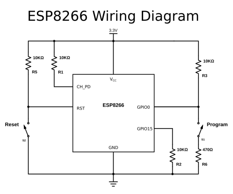
If you're using a bare-bone ESP-## board by AI Thinker, you have to add some resistors to turn on the ESP8266, and to select the right boot mode.
- Enable the chip by connecting the CH_PD (Chip Power Down, sometimes labeled CH_EN or chip enable) pin to VCC through a 10KΩ resistor.
- Disable SD-card boot by connecting GPIO15 to ground through a 10KΩ resistor.
- Select normal boot mode by connecting GPIO0 to VCC through a 10KΩ resistor.
- Prevent random resets by connecting the RST (reset) pin to VCC through a 10KΩ resistor.
- Make sure you don't have anything connected to GPIO2 (more information in the next chapter).
If your ESP8266 board doesn't have a reset button, you could add one by connecting a push button to between the RST pin and ground.
To put the chip into programming mode, you have to pull GPIO0 low during startup. That's why we also need a program button. Because it's possible to use GPIO0 as an output, we can't directly short it to ground, that could damage the chip. To prevent this, connect 470Ω resistor in series with the switch. It's important that this resistance is low enough, otherwise, it will be pulled high by the 10KΩ resistor we added in the previous paragraph.
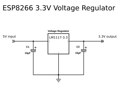
If the ESP8266 module you have doesn't have a 3.3V voltage regulator on board, you have to add one externally. You could use an LM1117-3.3 for example.
- Connect the first pin of the regulator to ground.
- Place a 10µF capacitor between pin 2 (Vout) and ground. Watch the polarity!
- Place a 10µF capacitor between pin 3 (Vin) and ground.
- Connect pin 2 to the 3.3V or VCCof the ESP8266.
- Connect pin 3 to a 5V power source, a USB port, for example.
There's a few things you have to look out for when using an ESP8266: The most important thing is that it runs at 3.3V, so if you connect it to a 5V power supply, you'll kill it. Unlike some 3.3V Arduino or Teensy boards, the ESP8266's I/O pins are not 5V tolerant, so if you use a 5V USB-to-Serial converter, or 5V sensors etc. you'll blow it up. A second thing to keep in mind is that the ESP8266 can only source or sink 12mA per output pin, compared to 20-40mA for most Arduinos. The ESP8266 has one analog to digital converter, but it has a strange voltage range: 0 - 1V, voltages above 1V might damage the board. One last thing to keep in mind is that the ESP8266 has to share the system resources and CPU time between your sketch and the Wi-Fi driver. Also, features like PWM, interrupts or I²C are emulated in software, most Arduinos on the other hand, have dedicated hardware parts for these tasks. For most applications however, this is not too much of an issue.
The first step is to download and install the Arduino IDE. I explained this in A Beginner's Guide to Arduino. (As of February 7th 2017, the latest stable version of the IDE is 1.8.1.)
To program the ESP8266, you'll need a plugin for the Arduino IDE, it can be downloaded from GitHub manually, but it is easier to just add the URL in the Arduino IDE:
- Open the Arduino IDE.
- Go to File > Preferences.
- Paste the URL http://arduino.esp8266.com/stable/package_esp8266com_index.json into the Additional Board Manager URLs field. (You can add multiple URLs, separating them with commas.)
- Go to Tools > Board > Board Manager and search for 'esp8266'. Select the newest version, and click install. (As of February 7th 2017, the latest stable version is 2.3.0.)
If you are using a board with the CH340(G) USB-to-Serial chip, like the NodeMCU, you'll probably have to install the USB drivers for it. They can be found on GitHub. If you are using a board with the CP2104 USB-to-Serial chip, like the Adafruit Feather HUZZAH board, you'll probably have to install USB drivers as well. You can find them on the Silicon Labs website. Boards with an FTDI chip should work right out of the box, without the need of installing any drivers.
If you want to use Over The Air updates on Windows, you have to install Python 2.7. You can download it from python.org. During the installation, you have to select the option to add Python to your path. If you don't do this, the Arduino IDE won't be able to find the Python executable.
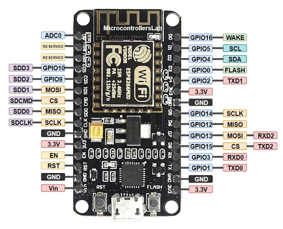
Just like a normal Arduino, the ESP8266 has digital input/output pins (I/O or GPIO, General Purpose Input/Output pins). As the name implies, they can be used as digital inputs to read a digital voltage, or as digital outputs to output either 0V (sink current) or 3.3V (source current).
The ESP8266 is a 3.3V microcontroller, so its I/O operates at 3.3V as well. The pins are not 5V tolerant, applying more than 3.6V on any pin will kill the chip.
The maximum current that can be drawn from a single GPIO pin is 12mA.
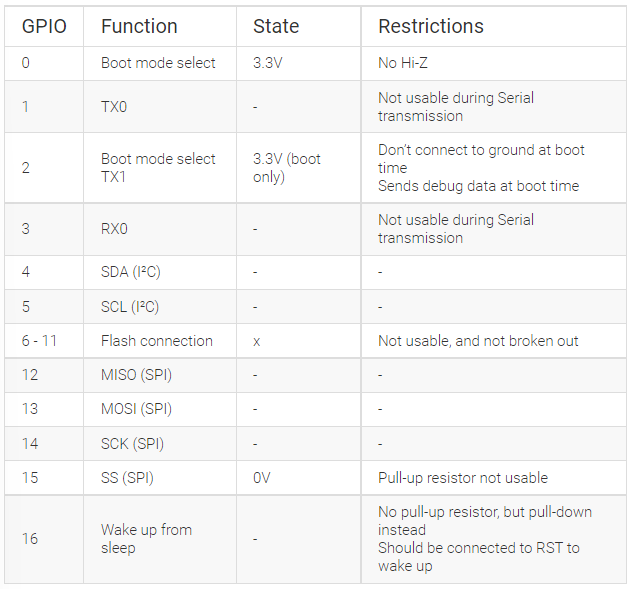
The ESP8266 has 17 GPIO pins (0-16), however, you can only use 11 of them, because 6 pins (GPIO 6 - 11) are used to connect the flash memory chip. This is the small 8-legged chip right next to the ESP8266. If you try to use one of these pins, you might crash your program. GPIO 1 and 3 are used as TX and RX of the hardware Serial port (UART), so in most cases, you can’t use them as normal I/O while sending/receiving serial data.
GPIO 0-15 all have a built-in pull-up resistor, just like in an Arduino. GPIO16 has a built-in pull-down resistor. As mentioned in the previous chapter, some I/O pins have a special function during boot: They select 1 of 3 boot modes:

Note: you don’t have to add an external pull-up resistor to GPIO2, the internal one is enabled at boot.
We made sure that these conditions are met by adding external resistors in the previous chapter, or the board manufacturer of your board added them for you. This has some implications, however:
-
GPIO15 is always pulled low, so you can’t use the internal pull-up resistor. You have to keep this in mind when using GPIO15 as an input to read a switch or connect it to a device with an open-collector (or open-drain) output, like I²C.
-
GPIO0 is pulled high during normal operation, so you can’t use it as a Hi-Z input.
-
GPIO2 can’t be low at boot, so you can’t connect a switch to it.
Internal pull-up/-down resistors
GPIO 0-15 all have a built-in pull-up resistor, just like in an Arduino. GPIO16 has a built-in pull-down resistor.
Unlike most Atmel chips (Arduino), the ESP8266 doesn’t support hardware PWM, however, software PWM is supported on all digital pins. The default PWM range is 10-bits @ 1kHz, but this can be changed (up to >14-bit@1kHz).
The ESP8266 has a single analog input, with an input range of 0 - 1.0V. If you supply 3.3V, for example, you will damage the chip. Some boards like the NodeMCU have an on-board resistive voltage divider, to get an easier 0 - 3.3V range. You could also just use a trimpot as a voltage divider. The ADC (analog to digital converter) has a resolution of 10 bits.
The ESP8266 has two hardware UARTS (Serial ports) UART0 on pins 1 and 3 (TX0 and RX0 resp.), and UART1 on pins 2 and 8 (TX1 and RX1 resp.), however, GPIO8 is used to connect the flash chip. This means that UART1 can only transmit data. UART0 also has hardware flow control on pins 15 and 13 (RTS0 and CTS0 resp.). These two pins can also be used as alternative TX0 and RX0 pins. #### I²C
The ESP doesn’t have a hardware TWI (Two Wire Interface), but it is implemented in software. This means that you can use pretty much any two digital pins. By default, the I²C library uses pin 4 as SDA and pin 5 as SCL. (The data sheet specifies GPIO2 as SDA and GPIO14 as SCL.) The maximum speed is approximately 450kHz. #### SPI
The ESP8266 has one SPI connection available to the user, referred to as HSPI. It uses GPIO14 as CLK, 12 as MISO, 13 as MOSI and 15 as Slave Select (SS). It can be used in both Slave and Master mode (in software). ### GPIO overview
where pin is the GPIO number, and mode can be either INPUT, which is the default, OUTPUT, or INPUT_PULLUP to enable the built-in pull-up resistors for GPIO 0-15. To enable the pull-down resistor for GPIO16, you have to use > __INPUT_PULLDOWN_16__
To set an output pin high (3.3V) or low (0V), use
digitalWrite(pin, value)
where pin is the digital pin, and value either 1 or 0 (or HIGH and LOW). To read an input, use
digitalRead(pin)
To enable PWM on a certain pin, use
analogWrite(pin, value)
where pin is the digital pin, and value a number between 0 and 1023. You can change the range (bit depth) of the PWM output by using
analogWriteRange(new_range)
The frequency can be changed by using
analogWriteFreq(new_frequency)
new_frequency should be between 100 and 1000Hz.
Just like on an Arduino, you can use analogRead(A0) to get the analog voltage on the analog input. (0 = 0V, 1023 = 1.0V). The ESP can also use the ADC to measure the supply voltage (VCC). To do this, include ADC_MODE(ADC_VCC); at the top of your sketch, and use ESP.getVcc(); to actually get the voltage. If you use it to read the supply voltage, you can’t connect anything else to the analog pin.
To use UART0 (TX = GPIO1, RX = GPIO3), you can use the Serial object, just like on an Arduino:
Serial.begin(baud).
Serial.begin(baud).
To use the alternative pins (TX = GPIO15, RX = GPIO13), use Serial.swap() after
Serial.begin.
To use UART1 (TX = GPIO2), use the Serial1 object.
All Arduino Stream functions, like read, write, print, println, ... are supported as well.
One thing to keep in mind while writing programs for the ESP8266 is that your sketch has to share resources (CPU time and memory) with the Wi-Fi- and TCP-stacks (the software that runs in the background and handles all Wi-Fi and IP connections). If your code takes too long to execute, and don’t let the TCP stacks do their thing, it might crash, or you could lose data. It’s best to keep the execution time of you loop under a couple of hundreds of milliseconds.
Every time the main loop is repeated, your sketch yields to the Wi-Fi and TCP to handle all Wi-Fi and TCP requests.
If your loop takes longer than this, you will have to explicitly give CPU time to the Wi-Fi/TCP stacks, by using including delay(0); or yield();. If you don’t, network communication won’t work as expected, and if it’s longer than 3 seconds, the soft WDT (Watch Dog Timer) will reset the ESP. If the soft WDT is disabled, after a little over 8 seconds, the hardware WDT will reset the chip.
From a microcontroller’s perspective however, 3 seconds is a very long time (240 million clockcycles), so unless you do some extremely heavy number crunching, or sending extremely long strings over Serial, you won’t be affected by this. Just keep in mind that you add the yield(); inside your for or while loops that could take longer than, say 100ms.
Using the ESP8266 as a simple microcontroller is great, but the reason why most people use it, is its Wi-Fi capabilities. In this chapter, we'll dive into the wonderful world of network protocols, like Wi-Fi, TCP, UDP, HTTP, DNS ... All these acronyms might intimidate you, but I'll try my best to explain them step-by-step and in an easy way. Some paragraphs are in italic. These provide some extra information, but are not critical to understanding the ESP's Wi-Fi functions, so don't get frustrated if there are things you don't understand. ### The TCP/IP stack
The system most people refer to as 'The Internet' isn't just one protocol: it's an entire stack of layers of protocols, often referred to as the TCP/IP stack. We'll go over these different layers, because we need to understand how our ESP8266 communicates with other devices on the network. 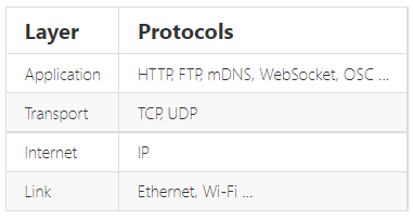
The link layer contains the physical link between two devices, an Ethernet cable, for example, or a Wi-Fi connection. This is the layer that is closest to the hardware. To connect an ESP8266 to the network, you have to create a Wi-Fi link. This can happen in two different ways: * The ESP8266 connects to a wireless access point (WAP or simply AP). The AP can be built-in to your modem or router, for example. In this configuration, the ESP acts like a wireless station. * The ESP8266 acts as an access point and wireless stations can connect to it. These stations could be your laptop, a smartphone, or even another ESP in station mode. Once the Wi-Fi link is established, the ESP8266 is part of a local area network (LAN). All devices on a LAN can communicate with each other. Most of the time, the AP is connected to a physical Ethernet network as well, this means that the ESP8266 can also communicate with devices that are connected to the AP (modem/router) via a wired Ethernet connection (desktop computers, gaming consoles and set-top boxes, for instance). If the ESP8266 is in access point mode, it can communicate with any station that is connected to it, and two stations (e.g. a laptop and a smartphone) can also communicate with each other. The ESP can be used in AP-only, station-only, or AP+station mode.
This only applies to boards without an on-board USB-to-Serial converter. If you don't have a USB-to-Serial converter with DTR and RTS lines, you could also just use the reset and program buttons we added in the hardware chapter. To get the ESP in program mode, GPIO0 must be low while booting: 1. press and hold the reset button 2. press and hold the program button 3. release the reset button, the ESP will boot in program mode 4. release the program button 5. upload the sketch
If you want to get out of program mode without uploading, just press reset (without pressing the program button).
If your specific board is in the Tools > Board list (e.g. NodeMCU, SparkFun and Adafruit boards), you can just select it, and you will get the right settings. When your board isn't in the list, you'll have to select a Generic ESP8266. In that case there's lots of new options in the Tools menu of the Arduino IDE, so let's go over them and pick the right settings.
Like I said before, the ESP8266 uses an external flash chip for storage. You can communicate with this chip over 2 datalines (DIO), or over all 4 datalines (QIO). Using 4 lines is two times faster than 2 lines, so in most cases, you should choose QIO. (If you're doing some advanced stuff and you need 2 more GPIO pins, you could use 2 lines instead of 4, and use the 2 lines as I/O. Most modules don't give you access to these pins, though. )
Different boards/modules have different sizes of flash chips on board. There are boards with 512kB, 1MB, 2MB and 4MB of flash. To know how much flash your board has, you can try the Examples > ESP8266 > CheckFlashConfig to see if your flash setting is correct, or you can check the specifications of your specific board online. You can also select the SPIFFS (SPI Flash File System) size. The SPIFFS partition is a small file system to store files. If you're not using it, you can select the minimum. Later on in the article, we'll use SPIFFS, and I'll remind you to select a larger SPIFFS size, but for now, it doesn't really matter.
There's a load of things going on when the ESP is running: Things like Wi-Fi connections, TCP connections, DNS lookups . All these small tasks produce a whole lot of debug output to help you troubleshoot. However, in a normal situation, where your program is behaving as expected, you don't need all those debug messages to flood the Serial Monitor, so you can just turn them off by selecting 'Disabled'.
As mentioned in the paragraphs above, there are different methods for auto-reset and auto-program. If you're using the first method (using the edge detector), you should use 'ck', if you use the two-transistor circuit, select 'nodemcu'.
If you need some extra memory speed, you could change the flash frequency from 40MHz to 80MHz. This is the clock frequency of the SPI/SDIO link.
If you need some extra CPU performance, you can double the clock speed from 80MHz to 160MHz. It's actually an overclock, but I've never had any issues or instability.
The baud rate for uploading to the ESP. The default is 115200 baud, but you can go higher (if you're changing your sketch a lot, it might be too slow). 921600 baud works most of the time, but you may get an error sometimes, if that's the case, switching back to 115200 will probably solve all problems.
Like I mentioned in the previous chapter, the ESP8266 can operate in three different modes: Wi-Fi station, Wi-Fi access point, and both at the same time. We'll start by looking at the configuration of a Wi-Fi station.
The code to connect to a wireless access point is relatively straightforward: enter the SSID and the password of the network you want to connect to, and call the WiFi.begin function. Then wait for the connection to complete, et voilà, your ESP8266 is now connected to your Local Area Network. #### PROOF
open the Serial monitor (CTRL+SHIFT+M) and upload the sketch. You should see something like this: 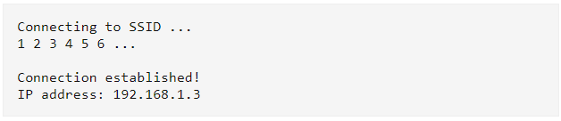
Now go to your computer and open up a terminal: On Windows, search for "Command Prompt", on Mac or Linux, search for "Terminal". You could also use the shortcuts: on Windows, hit + R, type "cmd" and hit enter, on Linux, use CTRL+ALT+T .
Next, type ping , and then the IP address you received in the Serial monitor. If you're on Mac or Linux, use CTRL+C to stop it after a couple of lines. The output should look something like this:
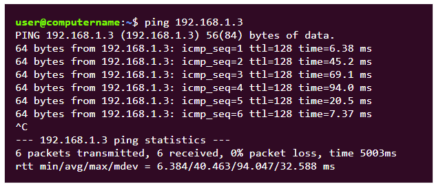
The ping command sends small packets to the IP address of the ESP8266. When the ESP receives such a packet, it sends it back to the sender. Ping is part of the second layer of the TCP/IP stack, the Internet layer. It relies on both the Data Link layer (Wi-Fi) and the Internet Protocol*. You can see that in the example above, we sent 6 packets to the ESP, and we also received 6 response (echo) packets. This tells us that the Data Link, the Wi-Fi connection, and the Internet Protocol are working correctly. We now know that the ESP can successfully communicate with other devices on the network, and if your local network is online (if it is connected to the Internet via your modem), the ESP can also communicate with any device on the web. Ping is a great tool to check if the ESP (or any device, really) is still connected to the network, and if it's still working fine.

The device with the antenna serves many different purposes: * Access point: Other Wi-Fi devices can connect to it, to be part of the local network. * Router: It routes IP packets to the right sub-nets so that they will arrive at their destination. E.g. if the computer sends a message that is meant for the ESP over the Ethernet sub-net, the router will send the packet to the Wi-Fi sub-net, because it knows that's where the ESP is. * Modem: if the router can't find the addressee on the local network, the packet will be passed on to the integrated modem, and it will be sent to the Internet Service Provider over a DSL line, heading for the Internet, where lots of other routers will try to get the packet to the right destination.
The sketch above might be enough for your specific application, but if you need to be able to connect to multiple Wi-Fi networks, for example the Wi-Fi at home and the Wi-Fi at the office, it won't work. To solve this problem, we'll use the Wi-Fi-Multi library: You can add as many networks as you like, and it automatically connects to the one with the strongest signal.
To see if it works, open the Wi-Fi settings on your computer, look for a network called "ESP8266 Access Point", enter the password "thereisnospoon", and connect to it. Then open a terminal, and ping to 192.168.4.1 (this is the default IP address of our ESP AP). You'll see that the ESP responds to your pings.
However, if you try to go to an online website, you'll get a timeout or a DNS error. This is because the ESP itself is not connected to the internet. The sub-net that consists of the ESP and the computer is not connected to any other networks, so there's no way for a packet on this network to make it to the Internet.
If you connected a second station to the ESP access point on the other hand, you would be able to ping from one station to the other without problems, because they're on the same network.
Let's face it, constantly typing IP addresses is really cumbersome, and it would be impossible to remember all your favorite websites' addresses, especially if they use IPv6. That's why domain names were introduced: a simple string of text that's easy to remember, for example www.google.com.
However, to send a request to a website, your computer still needs to know its IP address. That's where DNS comes in. It stands for Domain Name System, and is a way to translate a website's domain name to its IP address. On the Internet, there are a lot of DNS servers. Each DNS server has a long list of domain names and their corresponding IP addresses. Devices can connect to a DNS server and send a domain name, the DNS server will then respond with the IP address of the requested site. You could compare it to a telephone directory: you can look up a name to find the corresponding phone number.
The DNS lookup happens completely in the background: when you go to a website in your browser, it will first send a request to a DNS server (this implies that the computer knows the IP address of the DNS server itself), wait for the response of the lookup, and then send the actual request to the right IP address.
DNS works great for normal sites on the Internet, but most local networks don't have their own DNS server. This means that you can't reach local devices using a domain name, and you're stuck using IP addresses ...
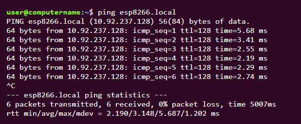
Fortunately, there's another way: multicast DNS, or mDNS. mDNS uses domain names with the .local suffix, for example http://esp8266.local. If your computer needs to send a request to a domain name that ends in .local, it will send a multicast query to all other devices on the LAN that support mDNS, asking the device with that specific domain name to identify itself. The device with the right name will then respond with another multicast and send its IP address. Now that your computer knows the IP address of the device, it can send normal requests.
mDNS is supported on Windows, OSX, Linux and iOS, but not (yet?) on Android. It's a real shame that Android doesn't support it, you can help by starring this issue report for the Chromium project to ask for mDNS support in Chrome on Android.
Of course, you can change the domain name of the ESP by changing the parameter of MDNS.begin.
ESP8266 Web ServerBeing able to ping the ESP is quite an achievement if you look at it from a technical point of view, but for most people, it's not that exciting, and not really useful.
In this chapter, I'll cover the basics of a web server, and teach you how to host a web page on the ESP. #### Web servers
A web server is an Internet-connected device that stores and serves files. Clients can request such a file or another piece of data, and the server will then send the right data/files back to the client. Requests are made using HTTP. ### HTTP
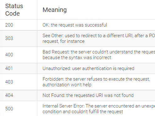
HTTP or the Hypertext Transfer Protocol is the text-based protocol used to communicate with (web) servers. There are multiple HTTP request methods, but I'll only cover the two most widely used ones: GET and POST.
GET requests are used to retrieve data from a server, a web page for instance. It shouldn't change anything on the server, it just gets the data from the server, without side effects. When you open a webpage in your browser, it will take the URL and put it in an HTTP GET request. This is just plain text. Then it will send the request to the right server using TCP. The server will read the request, check the URL, and send the right HTTP response for that URL back to the browser.
POST requests are used to send data to the server, for example, to send your user name and password to the server when you log in, or when you upload a photo. Unlike GET, POST can change the data on the server or the state of the server. POST has a body that can contain data that is sent to the server.
A server should answer all requests with an HTTP status code. This is a 3-digit number indicating if the request was successful or telling the client what went wrong. Here's a table with some of the most important and useful ones.