Repository navigation
Assembly
It's of course beneficial if you've worked with electronics and soldered before, otherwise this project is a good opportunity to learn 😉.
- get pcb (order from e.g. oshpark or aisler/ etch yourself)
- get needed components listed in bom
- order/ lasercut housing in 2 mm PMMA if desired. I admit it's not the nicest housing ever designed, so feel free to adjust provided file. This housing was a rough prototype providing cutouts to access relevant parts and was glued together only with tape on the sides.
- solder all parts on the pcb following the schematic
- start with lowest parts first
- insert ICs + Arduino into socket only after soldering
- take care of the correct LED-orientation (long lead = pos pin)
- connectors J6 & J7 are 6-pin box-connectors
- don't be confused if you board does not look like the one in the picture below, shown is a previous version of the board
- mount and fix board to mounting holes of housing floor, using, e.g., mounting spacers mentioned in bom
- insert and fix barrel connector and rocker switch to housing. Connect GND pin of barrel connector directly with GND of board. Connect + 12 V pin of barrel connector to switch (not important which pin), connect the other pin of the switch to VIn on board. Make sure to isolate connections with heat shrink tube (example seen in upper right of image).
- fix display (you need some screws which you might have at hand, they are not mentioned in the bom) + rotary encoder in enclosure top. Connect display and rotary encoder via jumper wires to respective pinheders on the board.
- place enclosure top on rest of enclosure and fix enclosure with tape/ screws
- flash firmware onto Arduino Nano via Arduino IDE
- the firmware makes use of following libraries, so make sure to install them before flashing (either via the library manager or by adding the .zip-library):
- LiquidCrystal_I2C (display control)
- CommandParser (parsing serial commands)
- MCP492X (DAC control)
- notes on the firmware:
- due to individual variations in hardware components a slight drift of the zero-value might occur. You can check for a drift by connecting a voltmeter to a signal-output (connect signal + ground), switch on the pacer and record the voltage in the idle state (pacing not turned on) U_idle. Then you can set the Variable DAC_correction in the code to U_idle/0.0062 (e.g. offset of +0.024 V -> DAC_correction = 0.024/0.0062 = 3.87 --> change line 74 to int DAC_correction = 4)
- unblocked pulse timing is currently controlled by calling millis(), which did not pose any issues for our applications (pulsewidths > 5 ms used). If timing is more crucial, calls to millis() might be replaced with micros().
- of course you don't need to use provided housing at all, you can also directly connect the input voltage to the board and start using it
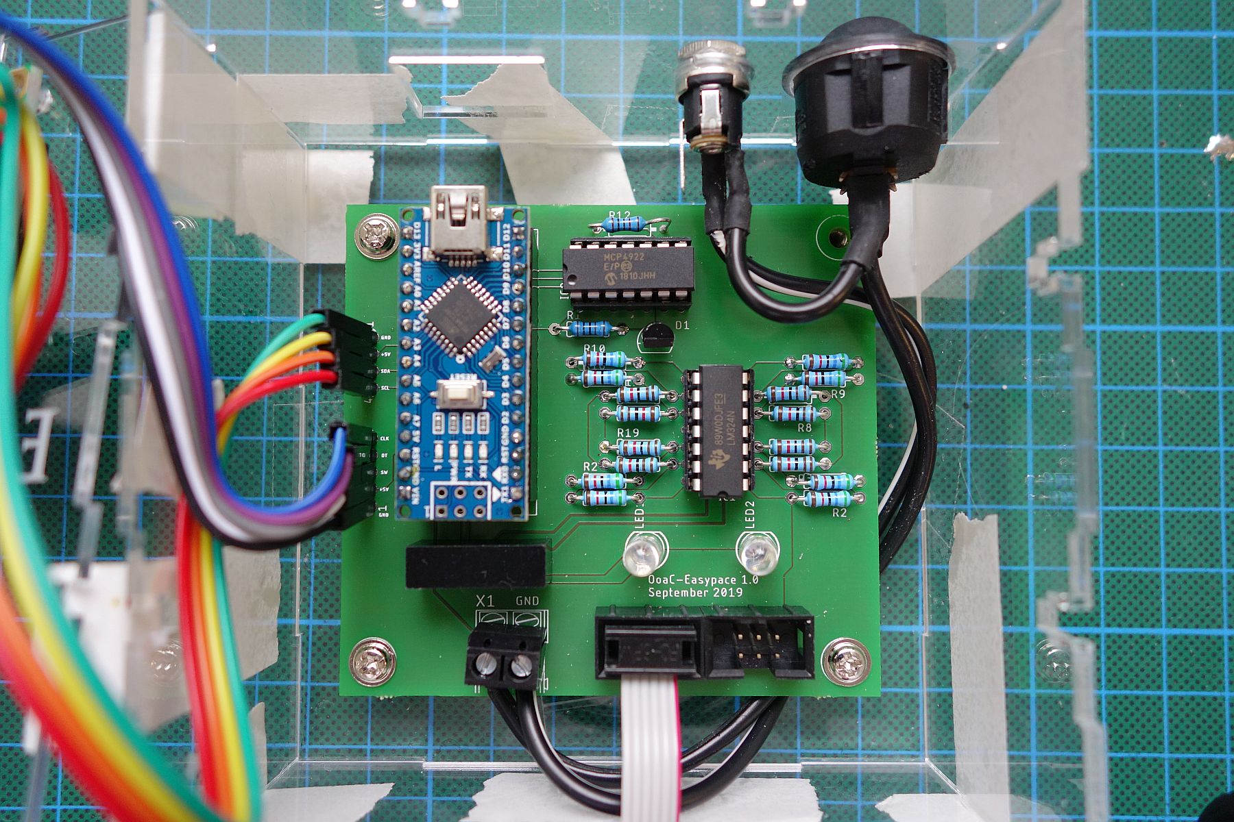
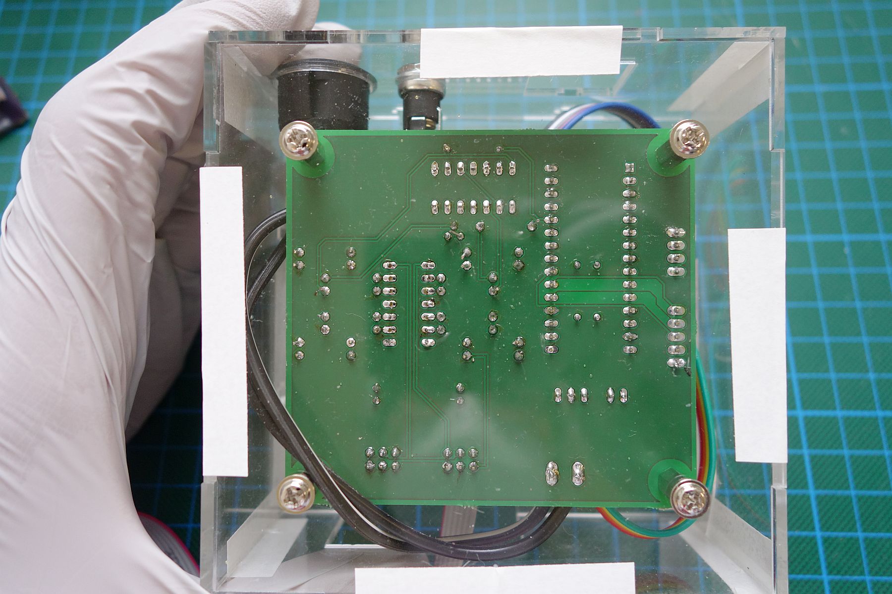
You can directly use the signal outputs from pinheaders of the pacer, or add an additional Connectorboard via a flat ribbon cable. The Connectorboard provides a simple interface to all 4 signals, such that connections to the sample can be easily adjusted by attaching alligator clips. A typical usecase is to place the pacer on a fixed spot and mount the connectorboard somewhere close to the samples (we used to use a 3d-printed holder where samples could be placed and where the connectorboard was directly mounted). Then the connectorboard can be, e.g., placed together with the samples into an incubator an can be connected via the flat ribbon cable to the pacer outside.
In general, the connectorboard provides the connection from the flatband cable to four 2-pin alligator clips. 100 Ohm resistors are added additionally to protect the pacing circuit of short-circuits. These resistors can be changed/ omitted if desired.
- get Connectorboard pcb
- get needed components listed in bom
- solder parts on pcb
- build pacer <-> Connectorboard cable:
- cut cable to desired length, take a piece of 6 cables
- lay cable into IDC socket, make sure pins match, close, e.g., in bench vise
- repeat on other side of cable, make sure pin layout is correct (cable at right side of one connector should also be on the right side of other connector)
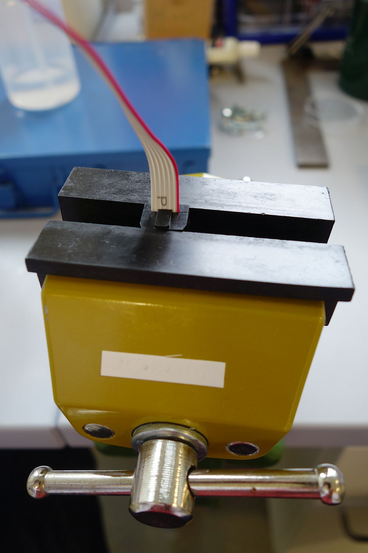
- build Connectorboard <-> sample connectors (with alligator clips):
- cut cables to desired length and isolate tips
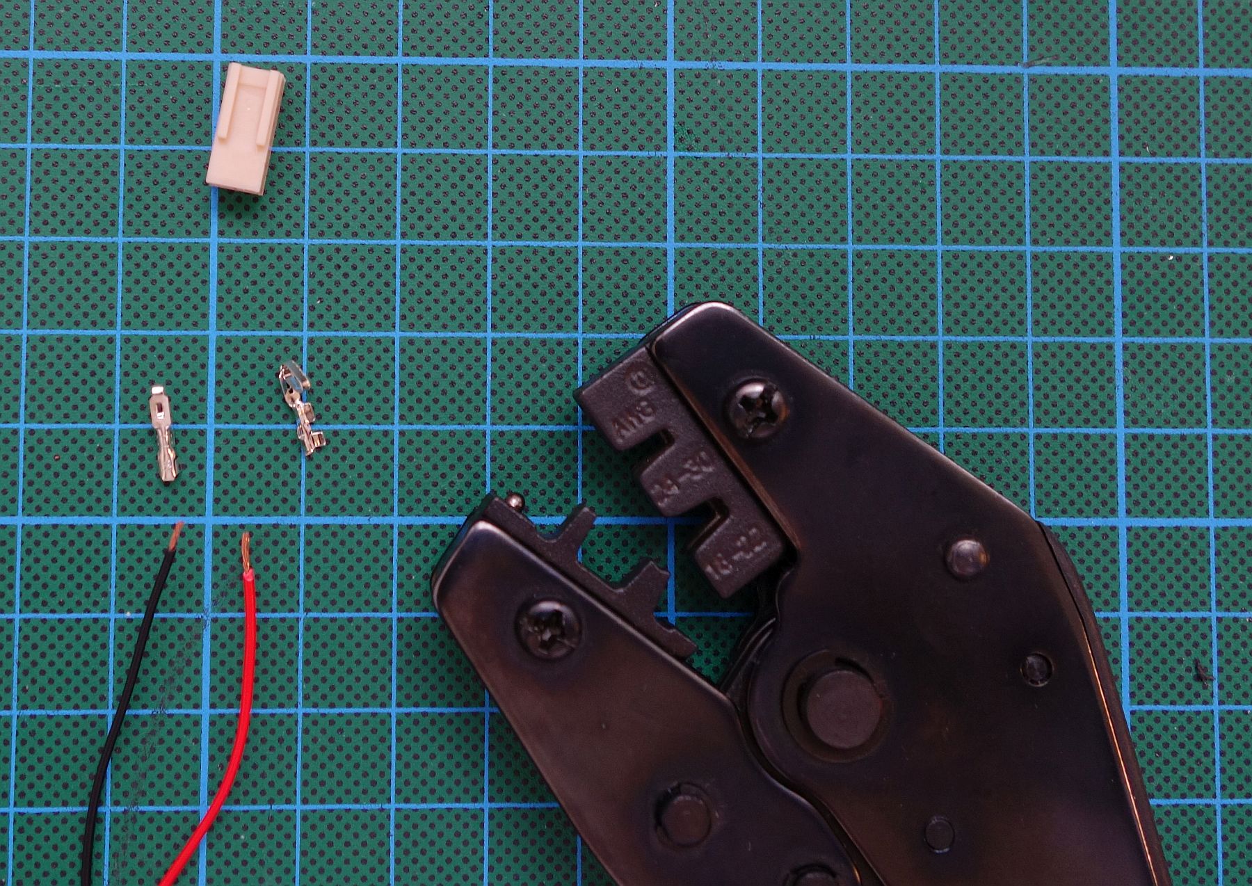
- crimp contacts on one side with crimping pliers
- place 2 crimped connectors into connector housing
- on other side: solder alligator clips to wires
After assembly, you should have following parts and everything is ready for performing experiments 🚀 :
