Repository navigation
Control
After assembly you should have following parts (Connector-PCB + cables only if wanted):

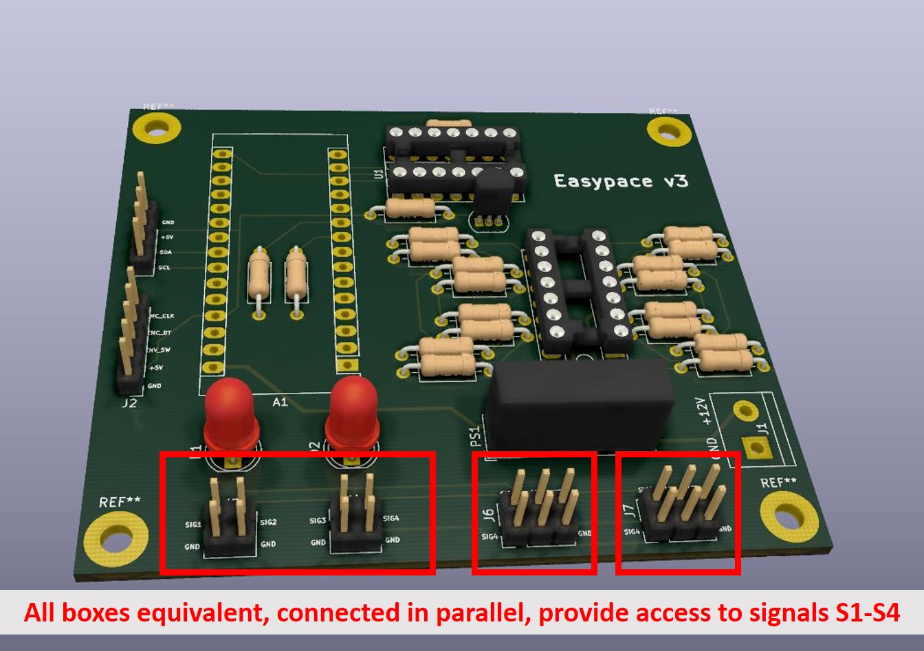
- as discussed you have multiple options to access the output signals
- either use jumper wires to directly grab signals (left box), or
- connect the Connectorboard via the ribbon cable to one of the box connectors (both boxes to the right. The rendering shows a pinheader, however a box connector should be actually soldered there)
- in general, the pacer controls 2 DAC-Outputs DAC1/DAC2 (-> 2 independent pacing parameters) which are translated to 4 signals: DAC1 -> S1/S2, DAC2 -> S3/S4, which means that signals S1+S2 (as well as S3+S4) are the same considering their waveform, however they are independent of each other (individual OpAmp outputs)
- in shown rendered view, all boxes are equivalent, i.e., provide access to all 4 signals S1-S4. Bear in mind, that the boxes are connected between each other in parallel. So if you connected 2 connectorboards to the right boxes simultaneously and use all signals on each board, you would also connect those samples in parallel during pacing (might work, not tested).
- possible connection of two connectorboards: connect connectorboard 1 with flatband cable and use only S1 + S2, connect connectorboard 2 with flatband cable and use only S3 + S4 (would also work with other permutation, e.g. use S1+S3 on board 1, S2+S4 on board 2)
- for using the connector board, connect one side of the flat ribbon cable to the pacer, the other side to the connectorboard
- connect the desired amount of alligator clips to the Connectorboard (up to 4 in current version) and contact your sample with the alligator clips
- connect the 12 V power supply and turn on back switch to place the pacer into an operating state
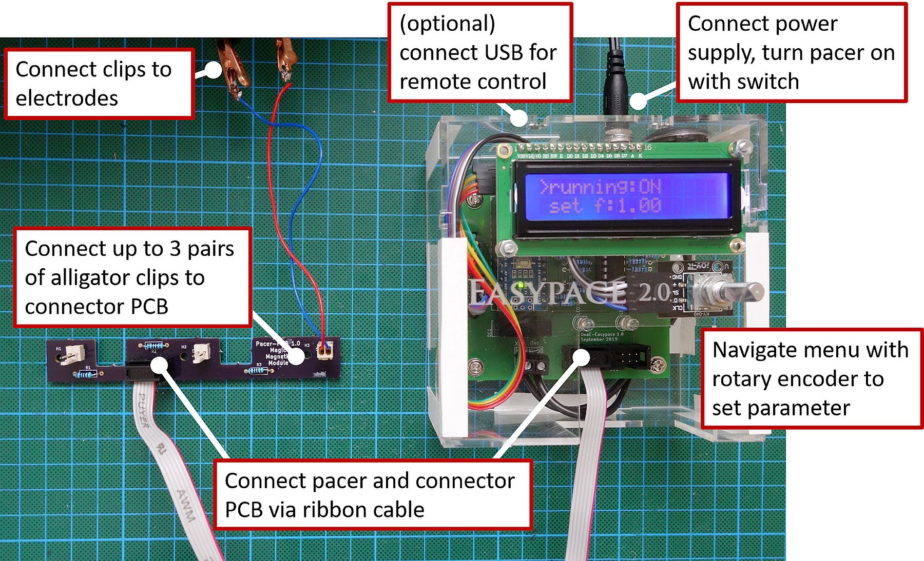
- navigate menu with rotary encoder (turn + push)
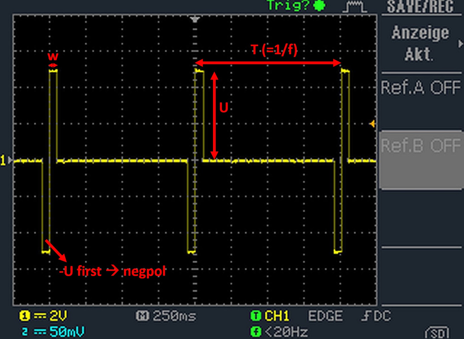
- you can set (cf. following annotated measured signal to clarify parameters)
- pacing on/ off
- pacing frequency f
- pacing voltage U
- pulsewidth w
- pacing polarity pol
- pacing is indicated by flashing LEDs which are synchronized to the output pulses and can be used for a visual control, if, e.g., synchronized tissue beating takes place
- in manual control, the output is the same for all signals S1-S4, there is no option to set individual parameters for S1+2 and S3+4.
By connecting the Arduino Nano via an USB-cable to a computer, you can control the pacer remotely. You need to establish a Serial connection to the virtual COM-Port where the Arduino is connected at baudrate 9600. Then you can send commands to the arduino and adjust all pacing parameters remotely:
- SETREM ON/OFF
- ON places pacer into remote mode -> no manual input accepted anymore
- OFF returns back to manual mode
- GETPAR
- returns current state of pacer
- SETON ON1 ON2:
- turn pacing on respective channel on, e.g.:
- SETON ON OFF -> pacing on DAC-channel 1 (=S1+S2),
- SETON ON ON -> pacing on DAC-channels 1+2 (=S1-S4),
- SETON OFF OFF -> pacing on no channel
- SETF f1 f2:
- specify pacing frequency for each channel, e.g.:
- SETF 0.5 2.0 -> frequency on DAC-channel 1 (S1+S2) = 0.5 Hz, on DAC-channel 2 (S3+S4)= 2.0 Hz
- SETU U1 U2:
- specify pacing voltage for each channel, e.g.:
- SETU 5.5 2.7 -> voltage on DAC-channel 1 (S1+S2) = 5.5 V, on DAC-channel 2 (S3+S4)= 2.7 V
- SETW w1 w2:
- specify pulsewidth for each channel, e.g.:
- SETW 5 50 -> pulsewidth on DAC-channel 1 (S1+S2) = 5 ms, on DAC-channel 2 (S3+S4) = 50 ms
- SETPOL pol1 pol2:
- specify pacing polarity for each channel, e.g.:
- SETPOL POS NEG -> polarity of first pulse on DAC-channel 1 (S1+S2) = positive, on DAC-channel 2 (S3+S4) = negative
You always need to specify parameters for both channels. You can establish a Serial connection either with the Aruino IDE, or with Tera Term.
If you want to run a longer experiment where you repeatedly vary pacing parameters, it makes sense to write a macro which executes desired commands.
You can use, e.g., Tera Term to write a macro in their "Tera Term Language (TTL)" to define a sequence of commands to the pacer. Some examples of macros controlling the pacer are listed in the scripts folder.
Another option for a scripted control of the pacer is writing the macro as a Python script, which gives you advanced control (e.g. if you want to simultaneously control a pump).
If you don't want to go through a full install of Python, or, e.g., need your institute's IT to provide you with admin right for an installation, you can also work with WinPython (e.g. WinPythonZero offers a version with small footprint), which is a portable Python version and does not need any installation. Just copy your script to the WinPython folder, open "WinPython Command Prompt.exe" and call python scriptname.py. Bear in mind, that you have to specify the correct COM-port in your script.
You can also find examples of Python scripts in the scripts folder