Hello, This repository will actually serve as a aid to help you get started with your own template. You should copy the raw form of this readme into your own, and use this template to write your own. If you want to draw inspiration from other classmates, feel free to check this directory of all students!.
- Table of Contents
- Hello_CircuitPython
- CircuitPython_Servo
- CircuitPython_LCD
- CircuitPython Distance Sensor
- Motor Control
- Temperature Sensor
- Rotary Encoder
- Photointerrupter
make the board print a color
Link to the code
import board
import neopixel

dot = neopixel.NeoPixel(board.NEOPIXEL, 1)
dot.brightness = 0.5

print("Make it red!")

while True:
    dot.fill((255, 0, 255))
image credit goes to josie muss
Make sure that the brightness on the Neopixel does not exceed 0.5 or it will hurt the eyeballs. You can use a color picker to find pleasant colors for the display.
make the servo perform a sweeping mtion back and forth 180 degrees
link to the code
from adafruit_motor import servo
import board
import pwmio
import time

pwm = pwmio.PWMOut(board.D3, duty_cycle=2 ** 15, frequency=50)

my_servo = servo.Servo(pwm)

while True:
    for angle in range(0, 180, 10):  # 0 - 180 degrees, 5 degrees at a time.
        my_servo.angle = angle
        time.sleep(0.05)
    for angle in range(180, 0, -10): # 180 - 0 degrees, 5 degrees at a time.
        my_servo.angle = angle
        time.sleep(0.05)


image credit goes to internet
This is not the full version of the assignment. This current state signifies half of the assignment, which allows the servo motor to perform a sweeping motion back and forth 180 degrees.
Make two inputs and use your LCD screen as an output device. Your Metro will count when one of the inputs is tripped, and the LCD will show the count. Your Metro should alternate between counting up and counting down when you touch the other input. The LCD should additionally show the count direction.
#original code credits go to Hazel Conklin view linked code https://github.com/honklin/Circuit-Python?scrlybrkr=9c8e9ad1#LCD

import board
import time
from lcd.lcd import LCD
from lcd.i2c_pcf8574_interface import I2CPCF8574Interface
from digitalio import DigitalInOut, Direction, Pull

i2c = board.I2C()
lcd = LCD(I2CPCF8574Interface(i2c, 0x3f), num_rows=2, num_cols=16)

up = DigitalInOut(board.D12) # up button
up.pull = Pull.UP
up.direction = Direction.INPUT

down = DigitalInOut(board.D13) # down button
down.pull = Pull.UP
down.direction = Direction.INPUT

count = 0
precount = -1 # placeholder for comparison
direction = " "
space = 0 # lcd spacing

while True:
    precount = count
    if (up.value): # counts up
        print("up")
        while (up.value):
            direction = "Up:"
        count += 1
        space = 4
    elif (down.value): # counts down
        print("down")
        while (down.value):
            direction = "Down:"
        count -= 1
        space = 6
    if (count != precount): # prevents holding counts
        lcd.clear()
        lcd.set_cursor_pos(0,0)
        lcd.print(direction) # print direction
        lcd.set_cursor_pos(0,space)
        lcd.print(str(count)) # print count
    time.sleep(.01)
https://user-images.githubusercontent.com/121810694/217867370-0524ab2c-ccad-4789-a559-7e34115aeb3d.GIF video credit goes to Haze in a Maze hazel conklin
When doing this assignment again, if the lcd is not printing, first check if the proper LCD is in place in the code. It could be
Print out the measurement of the distance to an object in cm on your serial display or LCD using the HC-SR04. Make the neopixel turn red if your object is less than 5 cm away, blue if it is between 5 and 20 cm away, and green if it is more than 20 cm away. The on-board neopixel's color should gradually change to match the distance.
#credit goes to Graham GS
#original code https://github.com/VeganPorkChop/CircutPython/blob/master/Sensorthing.py


# SPDX-FileCopyrightText: 2021 ladyada for Adafruit Industries
# SPDX-License-Identifier: MIT
import digitalio
import simpleio
import time
import board
import adafruit_hcsr04
import neopixel
from board import *

sonar = adafruit_hcsr04.HCSR04(trigger_pin=board.D3, echo_pin=board.D2)
Kaz = neopixel.NeoPixel(board.NEOPIXEL, 1)#connecting the neopixel on the board to the code
Kaz.brightness = 0.1  #setting the brightness of the light, from 0-1 brightness
KazOutput = 0
Red = 0
Green = 0
Blue = 0

while True:
    try:
        cm = sonar.distance
        print((sonar.distance, Red, Green, Blue))
        time.sleep(0.02)
        if cm < 5:
            Blue = 0
            Red = 255
            Kaz.fill((Red, 0, 0))#setting the color with RGB values
        if cm > 5 and cm < 10:
            Green = 0
            Red = simpleio.map_range(cm, 5.1, 10, 255, 0)
            Blue = simpleio.map_range(Red, 0, 255, 255, 0)
            Kaz.fill((Red, Green, Blue))
        else:
            Blue = simpleio.map_range(cm, 10.1, 20, 255, 0)
            Green = simpleio.map_range(Blue, 0, 255, 255, 0)
            Kaz.fill((0, Green, Blue))#setting the color with RGB values
    except RuntimeError:
        print("Retrying!")
    time.sleep(0.1)

image credit goes to ian novotne

Image credit goes to Benton House
when using the uultrasonic sensor it is ipmortant to not use a see through object or else the coordinates will get all wonky.
Connect a motor and a 6-volt battery pack to this circuit. The motor can be programmed to accelerate and decelerate in response to input from a potentiometer.
# orginial code credit goes to Cyrus Wyatt

import time
from time import sleep
import board
import simpleio
from analogio import AnalogIn
import pwmio

analog_in = AnalogIn(board.A1) #potentionmeter pin
pin_out = pwmio.PWMOut(board.D8,duty_cycle=65535,frequency=5000)
### Description
Wire up a 6v battery pack to this circuit w/ a motor.
Code something to make the motor speed up and slow down, based on input from a potentiometer.

### Codee

while True:

  sensor_value = analog_in.value
  # Map the sensor's range from 0<=sensor_value<=255 to 0<=sensor_value<=1023
  mapped_value = int(simpleio.map_range(sensor_value, 0, 65535, 0, 255))

  pin_out.duty_cycle = sensor_value
  print("mapped sensor value: ", sensor_value)
  time.sleep(0.1)

image credit goes to cyrus wyatt

Converting the values from the potentiometer value range to the motor value range was crucial for this project.
This assignment shows the temperature on an LCD using a temperature sensor.
# original code credits go to my friend honklin

import board
from lcd.lcd import LCD # lcd libraries
from lcd.i2c_pcf8574_interface import I2CPCF8574Interface
import analogio
import simpleio # map library
import time

i2c = board.I2C() # lcd declaration
lcd = LCD(I2CPCF8574Interface(i2c, 0x27), num_rows=2, num_cols=16)

tempSensor = analogio.AnalogIn(board.A0) # temperature sensor

temp = 74 # temperature
oldTemp = 0 # refresh variable
message = " "

while True:
    temp = int(simpleio.map_range(tempSensor.value,0,65535,32,212)) # maps values to Fahrenheit
    if (oldTemp != temp): # checks if needs to reprint lcd text
        if (temp <= 70): # higher than 70
         message = "Too cold!"
        elif (temp >= 78): # higher than 78
            message = "Too hot!"
        else: # 70-78
            message = "Just right"
        lcd.clear()
        lcd.set_cursor_pos(0,0)
        lcd.print(str(temp)) # prints temp
        lcd.set_cursor_pos(0,3)
        lcd.print("deg F")
        lcd.set_cursor_pos(1,0)
        lcd.print(message)
    oldTemp = temp
time.sleep(1)Temperature.Sensor.mp4
Video of LCD displaying changing temperature sensor values (video credit goes to my friend Honklin)
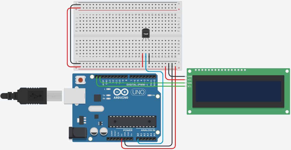 Wiring for Temperature Sensor
Finding the temperature measurements from the sensor proved to be the most difficult aspect of this assignment. Since there is no library for the temperature sensor, it was most helpful to declare it an analog pin and used analogio to find the data. It is also important to keep in mind that the SDA and SCL pins on the LCD screen correspond to the SDA and SCL pins on the Metro was also crucial.
This assignment changes traffic lights using a rotary encoder and displays the state on an LCD.
#original code goes to Hazel Chonklin

import board
from lcd.lcd import LCD # lcd libraries
from lcd.i2c_pcf8574_interface import I2CPCF8574Interface
import rotaryio # rotary encoder library
import digitalio # led library
import time

i2c = board.I2C() # lcd declaration
lcd = LCD(I2CPCF8574Interface(i2c, 0x27), num_rows=2, num_cols=16)

encoder = rotaryio.IncrementalEncoder(board.D3,board.D4) # rotary encoder potentiometer

button = digitalio.DigitalInOut(board.D2) # rotary encoder button
button.pull = digitalio.Pull.UP
button.direction = digitalio.Direction.INPUT

stop = digitalio.DigitalInOut(board.D13) # red led
stop.direction = digitalio.Direction.OUTPUT

caution = digitalio.DigitalInOut(board.D12) # yellow led
caution.direction = digitalio.Direction.OUTPUT

go = digitalio.DigitalInOut(board.D11) # green led
go.direction = digitalio.Direction.OUTPUT

position = 0 # modified position
states = ["stop", "caution", "go"] # states
state = " " # lcd print state
x = 0 # array selection

while True:
    prestate = state # uses for reprinting
    position = encoder.position % 20 # finds ticks from 0
    if (position < 7): # if stop
        x = 0
    elif (position > 12): # if go
        x = 2
    else: # if caution
        x = 1
    state = states[x] # sets state
    if (button.value == False): # if button is pressed
        stop.value = False
        caution.value = False
        go.value = False
        if (state == "stop"): # turns on correct light
            stop.value = True
        elif (state == "caution"):
            caution.value = True
        else:
            go.value = True
    if (state != prestate): # reprints lcd data
        lcd.clear()
        lcd.set_cursor_pos(0,0)
        lcd.print("Push for ")
        lcd.set_cursor_pos(0,9)
        lcd.print(state) # prints state
time.sleep(0.1)Rotary.Encoder.MOV
Video of rotary encoder selecting traffic states displayed on an LCD and turning on the correct LED (video credit goes to my friend Honklin)
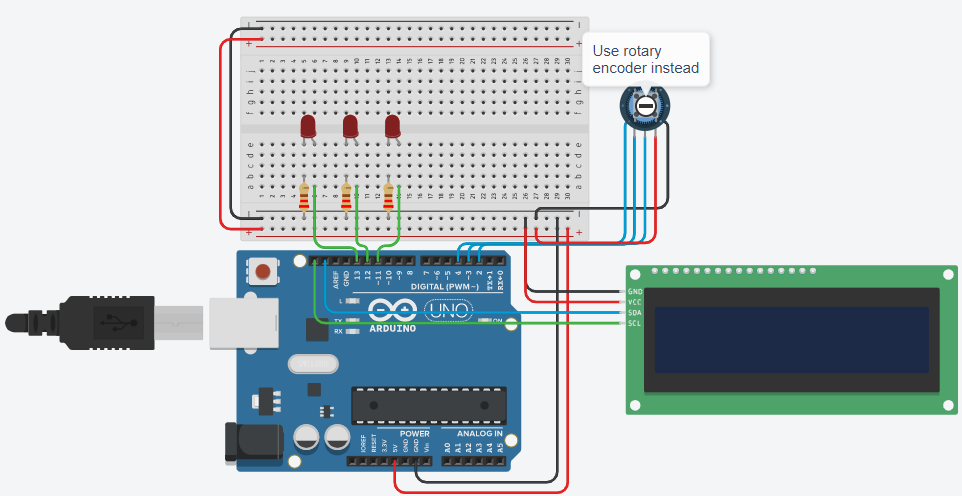 Wiring for Rotary Encoder (image credit goes to my friend Honklin)
Finding the library for rotary encoders was crucial for this assignment.To set the continuous rotation position, I used% to get the last 20 in the equation, after which I looked to see which third of the circle the encoder was in.
This assignment displays the number of times a photointerrupter is interrupted on an LCD screen every 4 seconds.
# OG code is hazel's

import board
from lcd.lcd import LCD # lcd liraries
from lcd.i2c_pcf8574_interface import I2CPCF8574Interface
import digitalio # use photointerrupter was digital input
import time

i2c = board.I2C() # lcd declaration
lcd = LCD(I2CPCF8574Interface(i2c, 0x27), num_rows=2, num_cols=16)

photo = digitalio.DigitalInOut(board.D2) # photointerrupter
photo.direction = digitalio.Direction.INPUT

interrupts = 0
now = time.monotonic() # keeps time without sleep()
increase = False

while True:
    while (photo.value == True): # loops while being interrupted
        increase = True
    if (increase == True): # only counts one per interrupt
        interrupts += 1
        increase = False
    if (time.monotonic() - now >= 4): # prints every 4 seconds
        lcd.clear()
        lcd.set_cursor_pos(0,0)
        lcd.print("The number of")
        lcd.set_cursor_pos(1,0)
        lcd.print("interrupts is ")
        lcd.set_cursor_pos(1,14)
        lcd.print(str(interrupts)) # prints number of interrupts
now = time.monotonic() # restarts countingPhotointerrupter.mp4
Video of LCD displaying the number of interrupts every 4 seconds (video credit goes to my friend Honklin)
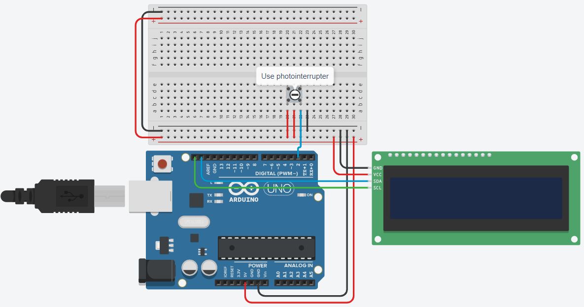 Wiring for Photointerrupter (image credit goes to my friend Honklin)
Since I was unable to locate a library for the photointerrupter, I designated it to be a digital input that would function similarly to a button in terms of sending input. Additionally, I discovered that if I increase the total before the photointerrupter has turned false, the code would continue counting until it is uninterrupted, thus I had to check the photointerrupter in a loop instead.