- Table of_Contents
- Hello_CircuitPython
- CircuitPython_Servo
- CircuitPython Distance Sensor
- CircuitPython_LCD
- Motor_Control
- Temperature_Sensor
- Rotary_Encoder
- Photointerrupter
- Assignment_Template
Make the LED blink.
import board #importing files
import neopixel
import time
import random

dot = neopixel.NeoPixel(board.NEOPIXEL, 1) #creates name(dot) for neopixels
dot.brightness =  .1 #sets neopixel brightness

print("Make it red!")

r = random.randint(0,255) #random integer between 0-225 for r(red)
g = random.randint(0,255) #random integer between 0-225 for g(green)
b = random.randint(0,255) #random integer between 0-225 for b(blue)
rgb = [r,g,b] #sets rgb value for random integers

if (r>200): #if r>200 g+b<80 in order to get more solid colors, less white
    g + b < 80

if (g>200): #same principle except for green
    r + b < 80

if (b>200): #same principle for these two except for blue
    g + r < 80

while True:
    dot.fill((rgb)) #make led randomly assigned rgb color
    time.sleep(.5)
    dot.fill((0,0,0))
    time.sleep(0.5)
```python
### Evidence
<details>
<summary>Click to Show</summary>

<p>

https://user-images.githubusercontent.com/91289646/192608483-b7759c1c-ec20-432e-8f1a-45b8bb5374d6.MOV

</p>

</details>

### Wiring
No wiring is required for this assignement.

### Reflection
Given that this was my first circuitpython assignemnt generally eveything was somewhat difficult given that it was all extremely new to me. I had to make sure I imoported all the files I use in this code. I had to look up the syntax required to get a random RGB value which was fairly easy. I also had to add lines 16-23 to the code beause I kept getting RGB values that made the LED all very dull colors.


## CircuitPython_Servo

### Description & Code
Make a 180 degree servo spin back and forth accordingly using two buttons.

```python
import time #importing files
import board
import pwmio
from adafruit_motor import servo
from digitalio import DigitalInOut,Direction,Pull
import simpleio

# create a PWMOut object on Pin 9.
pwm = pwmio.PWMOut(board.D7, duty_cycle=2 ** 20, frequency=40)

# Create a servo object, my_servo.
my_servo = servo.Servo(pwm)

btn = DigitalInOut(board.D4) #create button 1
btn2 = DigitalInOut(board.D3) #create button 2
btn.direction = Direction.INPUT #create button 1 direction
btn.pull = Pull.UP #pull up button 1
btn2.direction = Direction.INPUT #create button 2 direction
btn2.pull = Pull.UP #pull up button 2

while True:
    if not btn.value: #button 1 being pressed
        for angle in range(0, 180, 5):  # 0 - 180 degrees, 5 degrees at a time forward.
            my_servo.angle = angle
            time.sleep(0.05)
    if not btn2.value: #button 2 being pressed
        for angle in range(180, 0, -5): # 180 - 0 degrees, 5 degrees at a time backward.
            my_servo.angle = angle
time.sleep(0.05)Click to Show

I used some code off the internet to get the servo to start spinning. I was confused with how the range variable wokred but when I hovered over it in VSCode it was really helpful in explaining what it does. For the buttons I just stole the code from the CircuitPython_LCD assignment but just made two button variables by just putting a two next "btn: in each line.
Create a rainbow gradient with the LED as your your distance sensor reads closer and farther distances.
import time #import files
import board
import neopixel
import adafruit_hcsr04
from adafruit_hcsr04 import HCSR04
import simpleio

sonar = adafruit_hcsr04.HCSR04(trigger_pin=board.D6, echo_pin=board.D7) #initialize sonar sensor with pins
dot = neopixel.NeoPixel(board.NEOPIXEL, 1) #creates name(dot) for neopixels
dot.brightness =  .1 #sets neopixel brightness

while True:
    try:
        cm = sonar.distance #rewrite sonar distance
        print((cm)) #print sensor distance
        if cm>=5 and cm<=15: #if cm is between 5-15 range colors accordingly
            r=simpleio.map_range(cm,5,15,255,0) #red goes down
            g=simpleio.map_range(cm,5,15,0,0) #green is abscent
            b=simpleio.map_range(cm,5,15,0,255) #blue goes up
            print("Between 5 and 15")
            dot.fill((r,g,b)) #fills led with color
        elif cm>15 and cm<25: #if cm is betwwen 15-25 range colors accordingly
            r=simpleio.map_range(cm,15,25,0,0) #red is abscent
            g=simpleio.map_range(cm,15,25,0,255) #green goes up
            b=simpleio.map_range(cm,15,25,255,0) #blue goes down
            print("Between 15 and 25")
            dot.fill((r,g,b))
        else:  #prints not good if distance is between 5-25
            print("Not Good")
            dot.fill((0,0,0))
    except RuntimeError: #prints retrying if there's an error
        print("Retrying!")
time.sleep(.01)Click to Show

This assignment became much easier when breaking it down into smaller chunks. The main important part before the "while True:" is assigning "sonar" to the pin my distance sensor is connected to. After the "while True:" you just need to logically think about when each color comes in using the "simpleio.map_range". The LED should start off red and slowly go down, there should be no green and the blue should slowly come in. For the second half, there is no red, blue slowly fades out, and green will fade in. This all happens as you start close to your sensor and move out.
Create two inputs, one a button that causes a counter to change by x and two a second input that detrmines whether or not the counter goes up or down by x.
import board #imoprt all files
from lcd.lcd import LCD
from lcd.i2c_pcf8574_interface import I2CPCF8574Interface
import time
from digitalio import DigitalInOut, Direction, Pull
from analogio import AnalogIn
import simpleio

i2c = board.I2C() #get an i2c object
lcd = LCD(I2CPCF8574Interface(i2c, 0x27), num_rows=2, num_cols=16) #initiate LCD screen
ptmr = AnalogIn(board.A1) #identify potentiometer

btn = DigitalInOut(board.D7) #identify button
btn.direction = Direction.INPUT #identify button direction
btn.pull = Pull.UP #pull button up
counter = 0 #initialize counter
delta = 1 #initialize variable that counter changes by
lastBtn = btn.value #creates a second button value variable to call back to

while True:
    print(ptmr.value) #print potentiometer value
    lcd.set_cursor_pos(1,0) #set lcd cursor
    lcd.print(" Presses:") #print presses
    lcd.set_cursor_pos(1,12) #set lcd cursor
    lcd.print(str(counter)) #print counter
    lcd.print(" ") #removes excess integers after going between 9-11


    if ptmr.value<47000: #if potentiometer reads less than 47,000
        lcd.set_cursor_pos(0,0) #set cursor on lcd
        lcd.print("BTN State: Down  ") #print button state: down
        delta = -1 #set delta to -1
    else:
        lcd.set_cursor_pos(0,0) #set lcd cursor
        lcd.print("BTN State: UP    ") #print button state up
        delta = 1 #set delta to 1

    if not btn.value and lastBtn != btn.value: #if button is being pressed and button value is not the same as it was prior
        counter = counter + delta #add delta to counter

    lastBtn = btn.value #restating lastBtn
    time.sleep(0.05)
#problems: counts without button press
#zeros stay on the lcd when counting back from tenClick to Show
Uploading IMG_1397.MOV…

This one extremely difficult for me to understand exactly what my code was doing since I took some of it off the internet. I overcomplicated the code and created multiple if and elif statements that were unecessary. I ended up just needing an if and an else and a final if that would change the counter if the parameteres from the prior if and else were met. I still don't fully understand how the line "lastBtn = btn.value" works given that I define them as equal but then later call that my counter will only change if they aren't eqaul, but the code works and that's all that matters.
Make a DC Motor speed up and slow down using a potentiometer as the input.
import board #import files
import time
from analogio import AnalogOut, AnalogIn
import simpleio

motor = AnalogOut(board.A1) #motor ouput
ptmr = AnalogIn(board.A0) #potentiometer input

while True:
    print(simpleio.map_range(ptmr.value, 96, 65520, 0, 65535)) #print my potentiometer value
    motor.value = int(simpleio.map_range(ptmr.value, 96, 65520, 0, 65535)) #push potentiometer value to motor
    time.sleep(.1) #print delay
#Shoutout to Kazuo Shinozaki for providing such sweet and concise working code!Click to Show
Uploading IMG_1398.MOV…

I found this assignment really difficult given the lack of sample code online using DC Motors and circuit python. I was able to use a wiring diagram from last year to help me with wiring. I accidnetally used a faulty battery pack which set me back about 20 minutes until I got a new one. Given the lack of sample code, I couldn't really do the code for this and ended up using Kaz's code for this assignment.
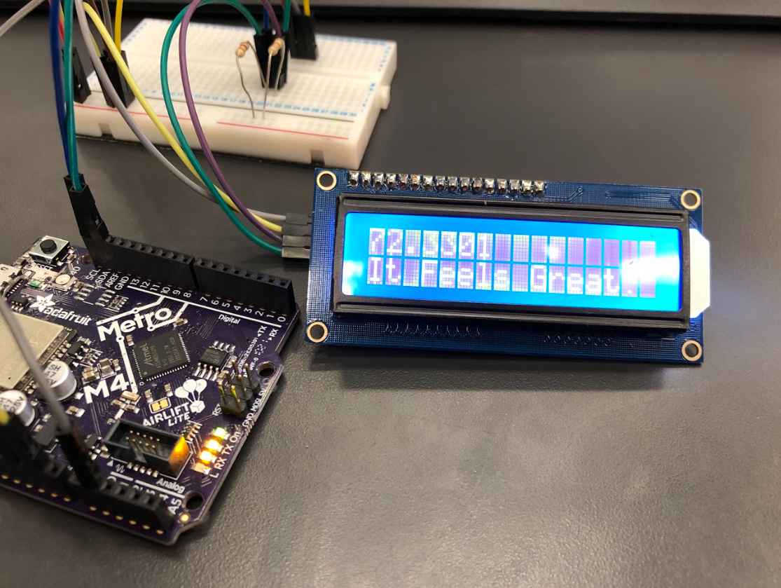
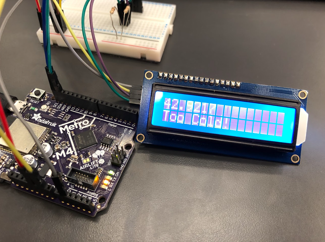
Use a Temperature Sensor and LCD to display the temperature in the room.
import board #imoprt all files
import time
from digitalio import DigitalInOut, Direction, Pull
from analogio import AnalogIn
from lcd.lcd import LCD
from lcd.i2c_pcf8574_interface import I2CPCF8574Interface
import simpleio

i2c = board.I2C() #get an i2c object
lcd = LCD(I2CPCF8574Interface(i2c, 0x27), num_rows=2, num_cols=16) #initiate LCD screen
temp = AnalogIn(board.A1)

while True:
    celsius = (simpleio.map_range(temp.value, 1023, 65535, 0, 125))
    fahrenheit = (celsius * (9/5)) + 32
    lcd.set_cursor_pos(0,0) #set lcd cursor
    lcd.print(str(fahrenheit)) #print temperature
    time.sleep(0.5)

    if temp.value > 80: #if the temperature is higher than 80 degrees
        lcd.set_cursor_pos(1,0) #set lcd cursor position
        lcd.print("Too Hot!                ") #print too hot on lcd
    elif temp.value < 50: #if the temperature is less than 50 degrees
        lcd.set_cursor_pos(1,0)
        lcd.print("Too Cold!                ") #print too cold on lcd
    else:   #if the temperature is greater than 50 and less than 80
        lcd.set_cursor_pos(1,0)
lcd.print("It Feels Great In Here! ") #print it feels great on lcd Click to Show

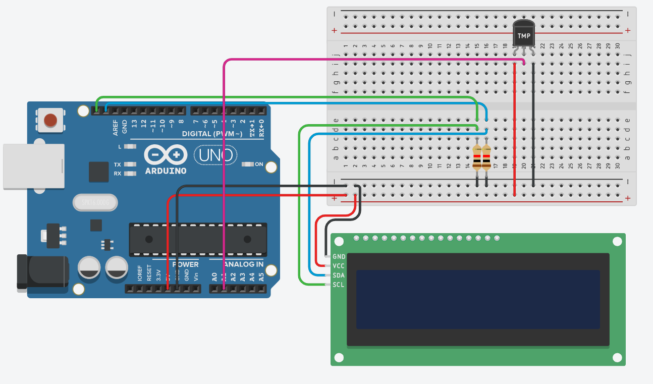
This assignment wasn't super hard since I was able to take all of my lcd code from a past assignment. The wiring was self explanitory for the exacty same reason as why the code was easy. The main issue I ran into was that my LCD screen didn't print anything I asked it to. The reason was the blue box on the back of the lcd backpack has a scew hole that needed to be turned in order to change the brightness contrast of the LCD so that the screen can actually be seen.
For this assignment we were told to use a rotary encoder which when integrated with an LCD screen and LED's act as a traffic light.
# Rotary Encodare light thingksf;ja
import time
import rotaryio
import board
from lcd.lcd import LCD
from lcd.i2c_pcf8574_interface import I2CPCF8574Interface
from digitalio import DigitalInOut, Direction, Pull


encoder = rotaryio.IncrementalEncoder(board.D3, board.D2)
last_position = 0
btn = DigitalInOut(board.D1)
btn.direction = Direction.INPUT
btn.pull = Pull.UP
state = 0
Buttonyep = 1


i2c = board.I2C()
lcd = LCD(I2CPCF8574Interface(i2c, 0x27), num_rows=2, num_cols=16)


ledGreen = DigitalInOut(board.D8)
ledYellow = DigitalInOut(board.D9)
ledRed = DigitalInOut(board.D10)
ledGreen.direction = Direction.OUTPUT
ledYellow.direction = Direction.OUTPUT
ledRed.direction = Direction.OUTPUT


while True:
    position = encoder.position
    if position != last_position:
        if position > last_position:
            state = state + 1
        elif position < last_position:
            state = state - 1
        if state > 2:
            state = 2
        if state < 0:
            state = 0
        print(state)
        if state == 0:
            lcd.clear()
            lcd.set_cursor_pos(0, 0)
            lcd.print("Go")
            ledGreen.value = True
            ledRed.value = False
            ledYellow.value = False
        elif state == 1:
            lcd.clear()
            lcd.set_cursor_pos(0, 0)
            lcd.print("Caution")
            ledYellow.value = True
            ledRed.value = False
            ledGreen.value = False
        elif state == 2:
            lcd.clear()
            lcd.set_cursor_pos(0, 0)
            lcd.print("Stop")
            ledRed.value = True
            ledGreen.value = False
            ledYellow.value = False
    if btn.value == 1:
        time.sleep(.1)
        Buttonyep = 1
last_position = positionClick to Show
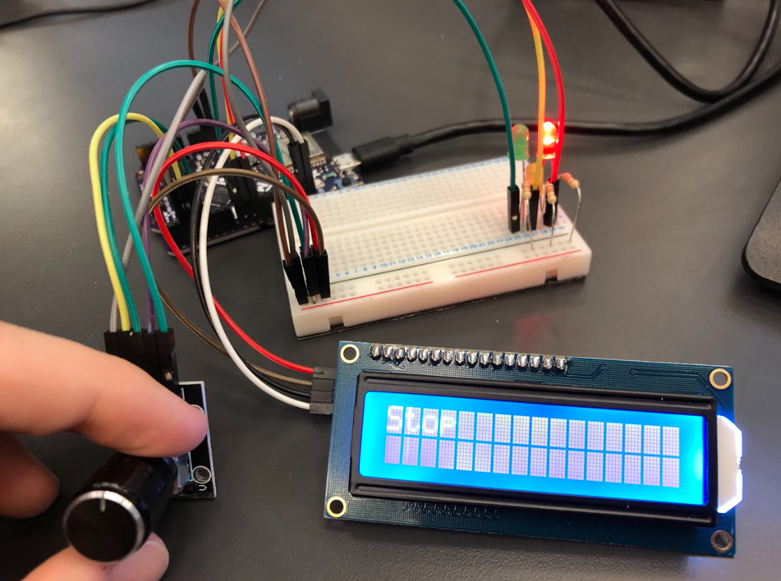
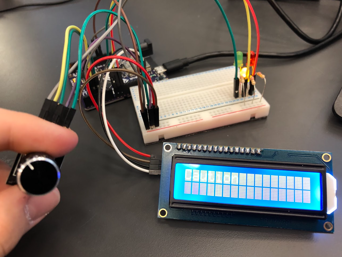
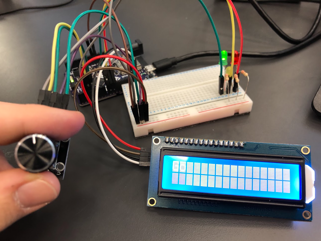
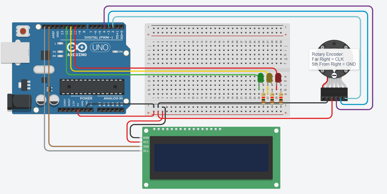
This assignemnt I found difficult beacuse we were provided with Arduino code to aid our creation of this assignment. I was never great at Arduino code and don't know its translation over to CircuitPython. I was able to find Kaz's code within the repository and used his encoder code. I wrote the rest of the code for my LED's to work for my configuration. I later found out that online resources were really helpful for this assignment and that it's always worth a look online for coding sources.
Use a photinerrupter and track the amount of interrupts on an LCD screen.
import time #imports
import rotaryio
import board
from lcd.lcd import LCD
from lcd.i2c_pcf8574_interface import I2CPCF8574Interface
from digitalio import DigitalInOut, Direction, Pull

i2c = board.I2C()
lcd = LCD(I2CPCF8574Interface(i2c, 0x27), num_rows=2, num_cols=16) #identify LCD screen

photoint = DigitalInOut(board.D7) #identify photointerrupter
photoint.pull =Pull.UP #pull up photointerrupter
counter = 0 #create counter set to zero

while True:
    if photoint.value == True: #if photointerrupter
        counter = counter + 1 #add to counter
        lcd.clear()
        lcd.color = [0, 100, 0]
        lcd.set_cursor_pos(0, 0) #set lcd cursor position
        lcd.print("Interrupts:" + str(counter)) #print interrupts and counter on lcd
        time.sleep(.5) #0.5sec delay
Click to Show
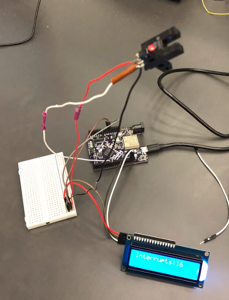
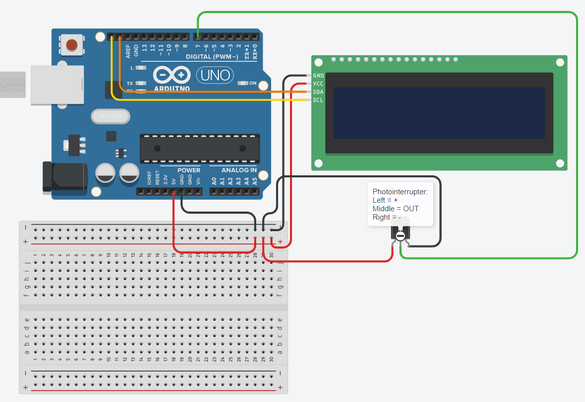
This assignement was super straight forward. All it requred was creating a counter and initalizing my photointerrupter as well as pulling it up. When the photointerrupter is interrupted the counter goes up by one. So all in all this was one of the easier assignements we've had to do this year.
Code goes hereClick to Show
(Evidence goes here!)