Support for GP1294ai Display #2213
Comments
|
Can you do a test with the other GP12xx constructors? What will you see? Which constructor works best? Could you sent an image? |
|
No function at all, the initial setting of the Gp1247/87 seems to be totally different. |
|
The main problem is: I am not the author of the GP12x7 displays... let's see... |
|
I had a deeper look into the specification, but to me it looks like that the documentation is kind of incomplete, for example the description for the 0xe0 cmd seems to be missing. Second problem is, that I am not able to read far east languages. Maybe @izilzty can give better comments here... |
|
Hi olikraus, it looks like GP1294 doesn't use 0x0e cmd. I think only needs to modify the init_seq and display_info of GP1287 to make it compatible with GP1294. I'll try to add support for GP1294, if I have time this week. The datasheet uploaded by @StephiB is not from Futaba, it should be made by someone else, because the display is a custom model, so there is no public datasheet, but the commands in it can still be referred to. |
Thanks, if you could do the init sequence suggestion, then I can do the remaining code changes. |
|
Fortunately, there are few differences between GP1294 and GP1287, I have finished modifying the code and simply tested it on Arduino & STM32, everything looks fine. I'll open a pull request later.
The init sequence of GP1294 is basically the same as that of GP1287, except for the commands 0xA0 (Dimming level Setting), 0x55 (Memory Map Clear) and 0xF0 (Display Data Write).
|

|
I can't express how much I'd love the GP1294 to be added to the list of supported displays. I have two of them that sellers sent me in error, that I can't get anything to work with. The project I am trying is a VFD clock that works with the GP1287... but it does not work with the GP1294 (using the ESP code plus the u8g2 libraries and selecting a GP1287, I get nothing on the display at all.. So I'm really glad to see this brought up. |
|
btw, if it helps.. I found some documentation on the GP1294AI and had it translated using google (and copied the html to my own site): Also, I noted there is some physical differences between the GP1287 and 1294... I noticed an added switching diode (A7W) on the 1294 just below R11 and to the left of the four capacitors. |
|
Hi medtech1, This is an Arduino library I created while testing the PR#2222, which includes support for the GP1294AI. GP1294AI supports these constructors: |
|
Hi.. thank you!
In the code I was using this line for the GP1287
U8X8_GP1287AI_256X50_4W_SW_SPI u8x8(/* clock=*/ 0, /* data=*/ 2, /* cs=*/ 14, /* dc=*/ 4, /* reset=*/16);
I think this is the equiv for the GP1294:
U8X8_GP1294AI_256X48_4W_SW_SPI u8x8(/* clock=*/13, /* data=*/11, /* cs=*/10, /* dc=*/U8X8_PIN_NONE, /* reset=*/8);
I have to read the docs to see if the change in numbers is GPIO pin?
Thanks
Michelle
On Tue, Jul 11, 2023, at 6:42 PM, izilzty wrote:
Hi medtech1, This is an Arduino library I created while testing the PR#2222 <#2222>, which includes support for the GP1294AI.
u8g2_arduino_2.35.2.zip <https://github.com/olikraus/u8g2/files/12022405/u8g2_arduino_2.35.2.zip>
You need to remove the current U8g2 library and install this zip library. But it should be noted that it is unofficial, when the official version supports GP1294AI, you can delete this library and reinstall the official version.
GP1294AI supports these constructors:
`U8G2_GP1294AI_256X48_1_4W_HW_SPI u8g2(U8G2_R0, /* cs=*/10, /* dc=*/U8X8_PIN_NONE, /* reset=*/8);
U8G2_GP1294AI_256X48_2_4W_HW_SPI u8g2(U8G2_R0, /* cs=*/10, /* dc=*/U8X8_PIN_NONE, /* reset=*/8);
U8G2_GP1294AI_256X48_F_4W_HW_SPI u8g2(U8G2_R0, /* cs=*/10, /* dc=*/U8X8_PIN_NONE, /* reset=*/8);
U8G2_GP1294AI_256X48_1_2ND_4W_HW_SPI u8g2(U8G2_R0, /* cs=*/10, /* dc=*/U8X8_PIN_NONE, /* reset=*/8);
U8G2_GP1294AI_256X48_2_2ND_4W_HW_SPI u8g2(U8G2_R0, /* cs=*/10, /* dc=*/U8X8_PIN_NONE, /* reset=*/8);
U8G2_GP1294AI_256X48_F_2ND_4W_HW_SPI u8g2(U8G2_R0, /* cs=*/10, /* dc=*/U8X8_PIN_NONE, /* reset=*/8);
U8G2_GP1294AI_256X48_1_4W_SW_SPI u8g2(U8G2_R0, /* clock=*/13, /* data=*/11, /* cs=*/10, /* dc=*/U8X8_PIN_NONE, /* reset=*/8);
U8G2_GP1294AI_256X48_2_4W_SW_SPI u8g2(U8G2_R0, /* clock=*/13, /* data=*/11, /* cs=*/10, /* dc=*/U8X8_PIN_NONE, /* reset=*/8);
U8G2_GP1294AI_256X48_F_4W_SW_SPI u8g2(U8G2_R0, /* clock=*/13, /* data=*/11, /* cs=*/10, /* dc=*/U8X8_PIN_NONE, /* reset=*/8);
U8X8_GP1294AI_256X48_4W_HW_SPI u8x8(/* cs=*/10, /* dc=*/U8X8_PIN_NONE, /* reset=*/8);
U8X8_GP1294AI_256X48_2ND_4W_HW_SPI u8x8(/* cs=*/10, /* dc=*/U8X8_PIN_NONE, /* reset=*/8);
U8X8_GP1294AI_256X48_4W_SW_SPI u8x8(/* clock=*/13, /* data=*/11, /* cs=*/10, /* dc=*/U8X8_PIN_NONE, /* reset=*/8);
`
…
—
Reply to this email directly, view it on GitHub <#2213 (comment)>, or unsubscribe <https://github.com/notifications/unsubscribe-auth/ADTWN2U2ID4SPJIWVFJSANDXPXXHVANCNFSM6AAAAAAZ2TTKJU>.
You are receiving this because you commented.Message ID: ***@***.***>
|
|
Just like other constructor, you only need to change the pin number to the actual use. For example, you can use: GP1287, GP1247 and GP1294 did not use dc pin, using |
|
Hey you rock.. it worked.
Thank you!!
On Tue, Jul 11, 2023, at 8:08 PM, izilzty wrote:
Just like other constructor, you only need to change the pin number to the actual use. For example, you can use:
`U8X8_GP1294AI_256X48_4W_SW_SPI u8x8(/* clock=*/ 0, /* data=*/ 2, /* cs=*/ 14, /* dc=*/ U8X8_PIN_NONE, /* reset=*/16);
`
… GP1287, GP1247 and GP1294 did not use dc pin, using `U8X8_PIN_NONE` instead of pin number.
—
Reply to this email directly, view it on GitHub <#2213 (comment)>, or unsubscribe <https://github.com/notifications/unsubscribe-auth/ADTWN2WWBEYJVQ2YHJ2UXW3XPYBJ3ANCNFSM6AAAAAAZ2TTKJU>.
You are receiving this because you commented.Message ID: ***@***.***>
|
|
Hey izilzty How can I get your email address? |
|
I don't know how to find the email address on github. Anyway, my email address is izilzty@outlook.com |
|
I am impressed... looks like all is solved.... wow... and there is also a PR. Impressive. |
|
Yes, and thank you all. |
Add support for GP1294AI, issue #2213
|
Thanks again for the PR. Excellent work :-) You can download the latest U8g2 beta release from here: https://github.com/olikraus/U8g2_Arduino/archive/master.zip
PlatformIO: |
|
I'm currently having issues with this too and honestly I do not know how to fix this. |
|
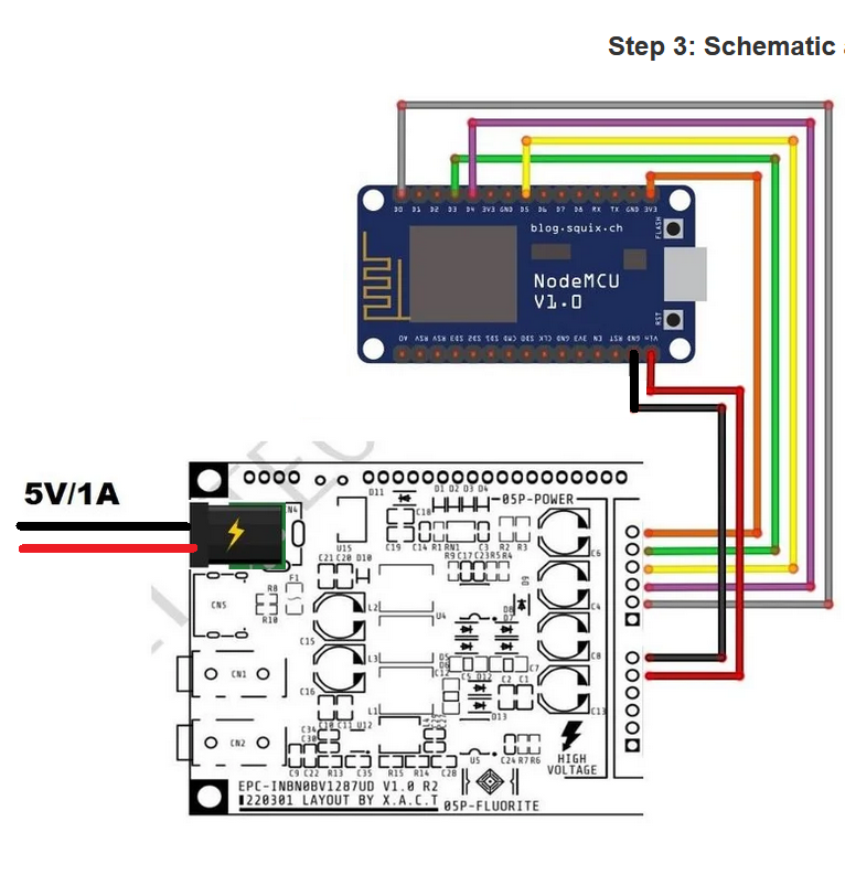
The pin-out on the NTP clock you are working with (per the URL you provided) is the same for both the GP1287 or GP1294: Conn Pin Color Destination(ESP) CN6 1 Black GND You just need to use: For the GP1287AI use: For the GP1294AI use: Also, once you program the ESP8266, pull out the USB cable from it and use just the 5v DC (min 1 amp) barrel connector (center positive) to provide power to the VFD. You do not need to feed the ESP with power as shown in the url you provided. The VFD will provide power to the ESP8266 through the jumper wires. Like this: http://redhat.systems/vfd/vfd-wiring.png btw, if the libraries aren't configured correctly it won't power on either. For instance, trying the GP1287AI library/constructs with the GP1294AI will just result in a non-responsive VFD.. it won't light up or anything. My GP1294AI worked right off using the construct above after removing the old library (that did not have GP1294 support) and installing the new one (with GP1294 support). |
|
I did not see a pin mapping anywhere and duckduckgo brought me here, so I'm just mentioning it for future search engine enthusiasts: Pins from the top to the bottom taken from this datasheet: |
|
RESET (grey in the instructable) was tied to D0, which did not work for me. I tied it to 3V3 (or probably any "HIGH" level) and it worked beautifully. Basically, all you need to connect is
Additionally, to have the VFD supply your microcontroller, you can use CN6 pin 2 (5V output). |
The chip select usually will put the SPI communication state machine into a defined state. So yes, usually it is required. Thanks for the updates and notes :-)
So, I hope you solved your problems with the help of u8g2 |
|
For now, I'm just playing around with an interesting display. But without u8g2, this would have been much more work. So: Thanks, everyone! :-) |
|
Im also having issues getting this to run on the Pico W and at this point im kinda frustrated and im not sure if its a faulty module or me messing up constantly - anyway i hope someone can help me here and point out where i messed up This is how i have wired the module up:
And this is the code im using: |
|
Hi Niphoria, I have no experience with Pico, but I think it might be necessary to set the polarity and phase of the SPI. You can try adding the following code after
And check the VFD FILMENT_EN and RESET pins, they seem to be connected to the DC pins, which is incorrect. You need to make sure FILMENT_EN is high and connect RESET to the PIN_RST pin of Pico that you defined. If FILMENT_EN is low, the filament will be turned off and nothing will be displayed on the screen. This is usually used to save power. If RESET is low, the screen enters reset state |
|
Hi izilzty, I applied your changes but sadly there is no sign of life on the VFD - is there any way i can test if the VFD module is even alive ? I have a power supply that can go up to 19V so i could apply it to the VFD display directly but i dont know if that would even be enough. here are my code changes |
|
After the program runs, if the filament in the display is dark red, it means that the power supply and FILMENT_EN pin are correct, and you may need to check the SPI wiring and program. If you are not sure the display is alive, you can try running the example program using a 3.3V Arduino board, the example program on the Arduino board should be correct and you can concentrate on troubleshooting hardware issues. |
|
Helo, I'm trying in vain to get this display to work with an ESP32 board. Use Arduino IDE to create programs. I think I'm connecting it incorrectly. I have the following board: https://mischianti.org/2021/02/17/doit-esp32-dev-kit-v1-high-resolution-pinout-and-specs/ I haven't even managed to create a character yet. U8G2 is master installed |
|
Hi, I have this ESP32 board too, maybe you should check the wiring again or try this example: Wiring:
Please connect the power supply of the VFD module and ESP32 by yourself, because our boards may be different. Code: After download and reset the ESP32, the VFD should show the U8g2 logo and the LED on the ESP32 board will flash. |
|
Hello, Thank you very much for the code and the pin assignment. It looks like I had a broken ESP32 and also a few others that no longer work. The built-in LED function is worth its weight in gold. Thank you for the help. What I wanted to ask was, have you ever played around with the brightness? Do you maybe know if it's full brightness in your code? |
|
The brightness in the code is the default value, which is not very bright, but enough for you to see what is on the screen. You can use |
|
Many thanks for the answer. But can you explain why your code works but the examples from the Arduino IDE don't? I also added your line, but unfortunately to no avail:
`#include <Arduino.h> #ifdef U8X8_HAVE_HW_SPI U8G2_GP1294AI_256X48_F_4W_SW_SPI u8g2(U8G2_R0, /* clock=/18, / data=/23, / cs=/25, / dc=/U8X8_PIN_NONE, / reset=*/33); // End of constructor list #define INFO_SCREEN_DELAY 3000 /* for period: c = 17 void setup(void) { void draw(int is_blank) for( j = 0; j < 20; j++ ) } void draw_m1_t() u8g2.setFontMode(1); u8g2.setCursor(0,15); u8g2.sendBuffer(); u8g2.setFontMode(1); void draw_m0_t() u8g2.setFontMode(1); u8g2.setCursor(0,15); u8g2.sendBuffer(); u8g2.setFontMode(0); void draw_m1_h() u8g2.setFontMode(1); u8g2.setCursor(0,15); u8g2.sendBuffer(); u8g2.setFontMode(1); void draw_m0_h() u8g2.setFontMode(1); u8g2.setCursor(0,15); u8g2.sendBuffer(); u8g2.setFontMode(0); void draw_m0_h_with_extra_blank() u8g2.setFontMode(1); u8g2.setCursor(0,15); u8g2.sendBuffer(); u8g2.setFontMode(0); void loop(void) { // This problem applies only to full buffer mode draw_m1_t(); // fontmode 1, t font --> wrong Thanks |
|
Line 17 has an incomplete block comment. You probably commented out all the code behind it. |
|
Yes, I only removed the commented one. Here is a small example from the Aurduino IDE, Helo World. Unfortunately, Helo World doesn't appear on the display, but your example works great. I'm not much of a code expert, so I don't really see what's going on... `/* HelloWorld.ino Universal 8bit Graphics Library (https://github.com/olikraus/u8g2/) Copyright (c) 2016, olikraus@gmail.com Redistribution and use in source and binary forms, with or without modification,
THIS SOFTWARE IS PROVIDED BY THE COPYRIGHT HOLDERS AND */ #include <Arduino.h> #ifdef U8X8_HAVE_HW_SPI /* */ // Please UNCOMMENT one of the contructor lines below // End of constructor list void setup(void) { void loop(void) { Thank you for Help |
|
Maybe you can attach the .ino file directly, it looks like there are a lot of "*" symbols missing in the code. Ignore this problem, the step to turn on the filament is missing in the code. If you don't want to control the filament, you can directly connect FILMENT_EN to 3.3V, but I still recommend using IO to control it to ensure that the high voltage and filament are started only after the code is running. |
|
Yes its works with Pin FILMENT_EN to 3.3. Im testing and learn about the display. Thank you for you Help, you are the best man. Thank You |
|
Hello, this is a ContrastTest (Filment on 3.3V) #include <Arduino.h> #ifdef U8X8_HAVE_HW_SPI U8G2_GP1294AI_256X48_F_4W_SW_SPI u8g2(U8G2_R0, /* clock=/18, / data=/23, / cs=/25, / dc=/U8X8_PIN_NONE, / reset=*/33); // End of constructor list void testContrast(uint8_t contrast) } while ( u8g2.nextPage() ); void setup(void) { /* U8g2 Project: SSD1306 Test Board */ /* U8g2 Project: T6963 Test Board */ u8g2.begin(); void loop(void) { |
|
I'm curious about increasing the brightness of the VFD, and it would affect the life of the VFD itself. I noticed in my tests that the GP1287BI runs much warmer than a GP1294AI (which the heat isn't very noticeable at all). Also, how much would the power consumption increase. The VFDs are very nice displays (and they work really well for me), but not sure if they would work very well in areas where there is bright sunlight. |
|
Sunlight may accelerate phosphorus failure, but this takes a long time, which may not be as fast as the pixel burn-in speed. |
|
One of the purposes of the VFDs is that to be used in bright sunlight where other technologies fail to deliver. |
|
@power-dodge I think this display has 1024 levels of brightness. |
|
The brightness input value is multiplied by 4 for remapping. Lines 129 to 130 in 711b504 |
|
Hello,
Dont work, i wil use 4 displays Thank you very much |
|
There should be an example in the u8g2 FAQ. |
|
Thanks, its works with _2, but its dont red more. I have 2 Displays istal, the Display nr. 2 its only works. I think the problem is on void setup: U8G2_GP1294AI_256X48_F_4W_SW_SPI u8g2_1(U8G2_R0, /* clock=*/18, /* data=*/23, /* cs=*/25, /* dc=*/U8X8_PIN_NONE, /* reset=*/33); //Screen 1
U8G2_GP1294AI_256X48_F_4W_SW_SPI u8g2_2(U8G2_R0, /* clock=*/18, /* data=*/23, /* cs=*/26, /* dc=*/U8X8_PIN_NONE, /* reset=*/33); //Screen 2`
void setup() {
Wire.begin();
u8g2_1.begin();
u8g2_2.begin();
}
void loop() {
u8g2_1.firstPage();
do{
u8g2_1.drawXBM(0,0,Honda_width,Honda_height,Honda_bits);
}while(u8g2_1.nextPage());
delay(1000);
u8g2_2.firstPage();
do{
u8g2_2.drawXBM(0,0,Honda_width,Honda_height,Honda_bits);
}while(u8g2_2.nextPage());
delay(1000); |
|
See the FAQ: Lines 293 to 300 in 2fca97d The reset line of the second object must be set to U8X8_PIN_NONE. |
|
Hello, thank you very much for the answer. I tried something around and until then it didn't work. The buffer thing will definitely be very problematic with 4 displays and only one ESP 32. I then decided to use a separate ESP32 for each display, which gives more flexibility etc. Today I tried to connect them with i2c, which wasn't that great either . |
|
Hello, I'm getting this error when verifying/compiling code but I'm not sure why: Compilation error: 'U8G2_GP1294AI_256X48_F_4W_SW_SPI' does not name a type; did you mean 'U8G2_GP1287AI_256X50_F_4W_SW_SPI'? I've got u8g2 version 2.34.22 installed in arduino ide. Not sure why it recognises the GP1287AI constructor but not the GP1294AI ? Has anyone seen this before or knows what's going wrong? I'm just using some simple test code: `/* HelloWorld.ino Universal 8bit Graphics Library (https://github.com/olikraus/u8g2/) Copyright (c) 2016, olikraus@gmail.com Redistribution and use in source and binary forms, with or without modification, Redistributions of source code must retain the above copyright notice, this list Redistributions in binary form must reproduce the above copyright notice, this THIS SOFTWARE IS PROVIDED BY THE COPYRIGHT HOLDERS AND */ #include <Arduino.h> #ifdef U8X8_HAVE_HW_SPI /* */ // Please UNCOMMENT one of the contructor lines below U8G2_GP1294AI_256X48_F_4W_SW_SPI u8g2(U8G2_R0, / clock=/18, / data=/23, / cs=/25, / dc=/U8X8_PIN_NONE, / reset=*/33); // End of constructor list void setup(void) { void loop(void) { |
|
Helo, |
|
Sorry ignore me, I should have read this thread more thoroughly - I had the standard library and not the beta one, it compiles now :) After swapping some wires around and whatnot and it's displaying some basic text, thanks a bunch for making the library guys and for the helpful info from everyone in this thread. |
Is it possible to add the GP1294AI VFD. I've tried to do it by myself but for some reason I can't get it to work.
Datasheet:
https://drive.google.com/file/d/1AG-xEty9XNawlXCaBtnWZ6uW1tDV3I1M/view?usp=drivesdk
Thanks in advance
The text was updated successfully, but these errors were encountered: