video.adoc: remove waffle, reorder #2541
Conversation
|
@andrum99 In future, could you please do any "rewording" and "reordering" in separate commits, as that'll make it easier to review what's actually changed. --- /tmp/old.txt 2022-07-06 08:59:48.215448150 +0100
+++ /tmp/new.txt 2022-07-06 09:00:13.447303953 +0100
@@ -2,12 +2,12 @@
==== `sdtv_mode`
-The `sdtv_mode` command defines the TV standard used for composite video output. On the original Raspberry Pi, composite video is output on the RCA socket. On other Raspberry Pis, except for Raspberry Pi Zero and Compute Module, composite video is output along with sound on the 4 pole TRRS ("headphone") socket. On the Raspberry Pi Zero, there is an unpopulated header labelled "TV" which outputs composite video. On the Compute Module, composite video is available via the TVDAC pin. The default value of `sdtv_mode` is `0`.
+The `sdtv_mode` command defines the TV standard used for composite video output. Composite is output on the 3.5mm AV jack, except on the Raspberry Pi 1B where it is output on the RCA jack.
|===
| sdtv_mode | result
-| 0
+| 0 (default)
| Normal NTSC
| 1
@@ -47,11 +47,9 @@
Setting `sdtv_disable_colourburst` to `1` disables colourburst on composite video output. The picture will be displayed in monochrome, but it may appear sharper.
-==== `enable_tvout` (Raspberry Pi 4 Model B Only)
+==== `enable_tvout`
-On the Raspberry Pi 4, composite output is disabled by default, due to the way the internal clocks are interrelated and allocated. Because composite video requires a very specific clock, setting that clock to the required speed on the Raspberry Pi 4 means that other clocks connected to it are detrimentally affected, which slightly slows down the entire system. Since composite video is a less commonly used function, we decided to disable it by default to prevent this system slowdown.
+Raspberry Pi 4 disables composite output unless you set this option to `1`: this will slow down the operation of the system slightly because of how internal clocks are inter-related. Because composite video requires a very specific clock, setting that clock to the required speed on the Raspberry Pi 4 means that other clocks connected to it are detrimentally affected.
-To enable composite output, use the `enable_tvout=1` option. As described above, this will detrimentally affect performance to a small degree.
-
-On older Raspberry Pi models, the composite behaviour remains the same.
+On Raspberry Pi Zero, 1, 2 and 3 this option can be set to `0` to prevent composite from becoming active when HDMI output is disabled.
So now my review-comments:
|
Apologies - will do.
Thanks - I will fix this.
I removed all discussion about composite that did not relate directly to the setting. I will reinstate the wording for Zero, since it is non-obvious and should be documented somewhere, but CM users should be curious enough to read the datasheet rather than rely on a passing reference in a tangentially related part of the documentation.
My proposed wording deliberately starts with Pi 4, since the difference on BCM2711-based boards was the reason for adding this setting, namely that composite is not available unless explicitly enabled via this setting. I have similar wording to yours for the older models. I'm not sure what happens if you set |
|
I've addressed the review comments, and added a small table showing what the default value of |
|
Just a quick note to say that I have left out any discussion of where the composite output is on the Pi Zero. The reason for this is that the Zero is already called out as having composite, so this should be enough given that the purpose of this section of the documentation is to describe the config.txt settings, not explain the Zero product itself. I'm happy to add mention of where the composite output is on the Zero if you prefer. |
|
I've finished polishing now - ready for further review. |
Given that you specifically call out Raspberry Pi 1, IMHO it also makes sense to call out Raspberry Pi Zero. I agree that the Compute Modules can probably be left out. |
Done. |
I'm assuming the silk screen on the Zero 2 W has the |
|
Just for completeness I tested the effect of |
|
Spotted a minor grammar issue, where a sentence could be misinterpreted. That's it ready now, I promise. |
|
|
||
| Set to `1` to enable composite video output, or `0` to disable. On Raspberry Pi 4, composite output is only available if you set this to `1`. | ||
|
|
||
| On Raspberry Pi Zero, 1, 2 and 3, composite output will be enable if HDMI output is disabled. HDMI output is disabled when no HDMI display is detected, or `hdmi_ignore_hotplug=1` is set. Set `enable_tvout=0` to prevent composite being enabled when HDMI is disabled. |
There was a problem hiding this comment.
Still need to change "will be enable" to "will be enabled".
|
|
||
| On Raspberry Pi Zero, 1, 2 and 3, composite output will be enable if HDMI output is disabled. HDMI output is disabled when no HDMI display is detected, or `hdmi_ignore_hotplug=1` is set. Set `enable_tvout=0` to prevent composite being enabled when HDMI is disabled. | ||
|
|
||
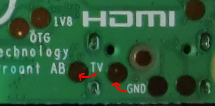
| On Raspberry Pi Zero, composite output is available on the unpopulated `TV` header. On Raspberry Pi Zero 2 W, composite output is available via test points on the underside of the board. |
There was a problem hiding this comment.
Should this line be right next to the "Composite is output on the 3.5mm AV jack..." line?
They are labelled on the silkscreen, but (IMHO) the test pads are all so close together that it's tricky to tell which pad is which, without the use of the diagram I pointed at. |
|
Can you confirm that the below image is correct? The two test pads in question look fine to me in that image. Also, if the image is correct, then the diagram is wrong. |
Yes, that's what the back of my Raspberry Pi Zero 2 W looks like too.
What makes you think the diagram is wrong? The position of the silkscreen labels perhaps isn't ideal, but it does tally up with the diagram at https://www.raspberrypi.com/documentation/computers/raspberry-pi.html#raspberry-pi-zero-2-w |
The fact that the Do we actually know which pads are I don't know what the reason is for the wonky labelling of the test pads - the fact I still got it wrong with both the diagram and looking at the underside of the board would tend to suggests the silk screen needs updated to correctly label the pads. |
These are test points used in production, the diagram was drawn using the measurements in the actual test positioning file. They're in the right place. I think what's fooling you in the diagram doesn't show all of the TP. |
Probably if I had an actual board to look at I would not have made that mistake - it's not a good image. There may be a good reason why the silk screen labels have been placed the way they have, but they are less than helpful. |
|
Here's a better image: https://pbs.twimg.com/media/FC0fDOnaQAAzLJV?format=jpg&name=large And it still looks as though the gap between these two pads is slightly less than the diameter of each pad. By contrast, the diagram shows the pads slightly further apart than the diameter of the each pad. But my error in understanding came from thinking that the |
|
My thinking is that this one is ready to go, although there is an issue over exactly which pads are My suggested fix to the issue of being unable to figure out exactly which test pad is which, is simply to update the silk screen so the |
The pads are correct according to both the images you've posted and the diagram in the documentation. I'm not sure where the confusion is? |
|
My confusion comes from the fact that the |
It's only you that's uncertain, not "we".
The test-pads on the back of the actual Zero 2 W have different diameters, but for simplicity they're all drawn at the same size in the diagram.
There's still the two outstanding issues that I pointed out several days ago - "will be enable" should be "will be enabled", and the bit talking about the Zero 2 W composite output ought to be moved next to the part talking about the 3.5mm AV jack. |
Apologies - I got mixed up. I have now fixed these two issues. The paragraph describing where composite is on each model is now rather complicated - I'm wondering if it might be better to replace it with a table? |
|
I've added the proposed table, which reminded me there is also the Pi 400 so I've added a note about that, and moved discussion of where composite can be found to after the table for the sdtv_mode setting. I think this is an improvement. I'm wondering if composite might be available internally on the Pi 400 board, but I'm not sure if it is worth mentioning that. |
|
Looking better, but it probably makes sense to move the "where composite video output can be found" section to between the "Composite Video Mode" and |
Done. |
|
Sorry to keep nitpicking, but it's just occurred to me that with "Raspberry Pi Zero" and "Raspberry Pi Zero 2 W" being separate things, the "Raspberry Pi Zero, 1, 2 and 3" phrasing is potentially ambiguous / confusing? Just as a reminder, https://www.raspberrypi.com/products/#raspberry-pi-computers-and-microcontrollers shows our "official product nomenclature". |
|
I've reworded things to remove the need to specifically name each model which enables composite when HDMI is disabled, since the list of models was getting rather long and unwieldy. Instead, it just says |
|
|
||
| Set to `1` to enable composite video output, or `0` to disable. On Raspberry Pi 4, composite output is only available if you set this to `1`. Composite output is not available on the Raspberry Pi 400. | ||
|
|
||
| On all models except Pi 4 and Pi 400, composite output will be enabled if HDMI output is disabled. HDMI output is disabled when no HDMI display is detected, or `hdmi_ignore_hotplug=1` is set. Set `enable_tvout=0` to prevent composite being enabled when HDMI is disabled. |
There was a problem hiding this comment.
If you can change "Pi 4 and Pi 400" to "Raspberry Pi 4 and Raspberry Pi 400" I think this PR might be good to go?
There was a problem hiding this comment.
If you can change "Pi 4 and Pi 400" to "Raspberry Pi 4 and Raspberry Pi 400" I think this PR might be good to go?
Done.
|
Ready to merge @lurch ? |
|
Yup, LGTM now 👍 This is now the "actual diff": --- /tmp/old.txt 2022-07-18 10:56:19.996387105 +0100
+++ /tmp/new.txt 2022-07-18 10:56:40.364274377 +0100
@@ -1,13 +1,33 @@
=== Composite Video Mode
+The table below describes where composite video output can be found on each model of Raspberry Pi computer:
+
+|===
+| model | composite output
+
+| Raspberry Pi 1 A and B
+| RCA jack
+
+| Raspberry Pi Zero
+| Unpopulated `TV` header
+
+| Raspberry Pi Zero 2 W
+| Test pads on underside of board
+
+| All other models
+| 3.5mm AV jack
+|===
+
+NOTE: Composite video output is not available on the Raspberry Pi 400.
+
==== `sdtv_mode`
-The `sdtv_mode` command defines the TV standard used for composite video output. On the original Raspberry Pi, composite video is output on the RCA socket. On other Raspberry Pis, except for Raspberry Pi Zero and Compute Module, composite video is output along with sound on the 4 pole TRRS ("headphone") socket. On the Raspberry Pi Zero, there is an unpopulated header labelled "TV" which outputs composite video. On the Compute Module, composite video is available via the TVDAC pin. The default value of `sdtv_mode` is `0`.
+The `sdtv_mode` command defines the TV standard used for composite video output:
|===
| sdtv_mode | result
-| 0
+| 0 (default)
| Normal NTSC
| 1
@@ -47,12 +67,23 @@
Setting `sdtv_disable_colourburst` to `1` disables colourburst on composite video output. The picture will be displayed in monochrome, but it may appear sharper.
-==== `enable_tvout` (Raspberry Pi 4 Model B Only)
+==== `enable_tvout`
-On the Raspberry Pi 4, composite output is disabled by default, due to the way the internal clocks are interrelated and allocated. Because composite video requires a very specific clock, setting that clock to the required speed on the Raspberry Pi 4 means that other clocks connected to it are detrimentally affected, which slightly slows down the entire system. Since composite video is a less commonly used function, we decided to disable it by default to prevent this system slowdown.
+Set to `1` to enable composite video output, or `0` to disable. On Raspberry Pi 4, composite output is only available if you set this to `1`. Composite output is not available on the Raspberry Pi 400.
-To enable composite output, use the `enable_tvout=1` option. As described above, this will detrimentally affect performance to a small degree.
+On all models except Raspberry Pi 4 and Raspberry Pi 400, composite output will be enabled if HDMI output is disabled. HDMI output is disabled when no HDMI display is detected, or `hdmi_ignore_hotplug=1` is set. Set `enable_tvout=0` to prevent composite being enabled when HDMI is disabled.
-On older Raspberry Pi models, the composite behaviour remains the same.
+[%header,cols="1,1"]
+
+|===
+|Model
+|Default
+
+|Pi 4 and 400
+|0
+
+|All other models
+|1
+|=== |
Get rid of some waffle which I wrote a few years ago, move composite below HDMI but above
LCD Displays and Touchscreenssection, which is for displays attached via the DSI connector. The pin name that composite is on has changed for CM4 too, so the existing paragraph contains an error in that regard.You may prefer me to add a table documenting where the composite output is on each model, rather than just removing this information.
The reason I have left a description of where composite is output on
most modelsis that there is no way to tell by looking at a Pi where composite is output, or even that it can output composite. (Apart from the original Pi 1B and 1A which have an RCA jack, but the function of these ports is not noted on the silk screen, and some of the RCA jacks are black, not yellow). The only exception is the Pi Zero (not Zero 2) which says 'TV' next to an unpopulated header on the top of the board (and perhaps not all models of Zero).