Creating Your First FLIP Fluids Simulation
In this guide, you will learn how to create a basic fluid simulation scene using the FLIP Fluids addon. In this simple scene, you will learn how to create a FLIP Fluid domain and add an inflow that emits fluid toward an obstacle object.

The Blend file (my_first_simulation.blend) for this scene can be downloaded here:
-
Blender 2.8+, 2.9+:
my_first_simulation-2.8.blend -
Blender 2.79:
my_first_simulation-2.79.blend
To follow this guide effectively, you will need:
- A basic understanding of how to use Blender and its user interface
- An installation of the FLIP Fluids addon
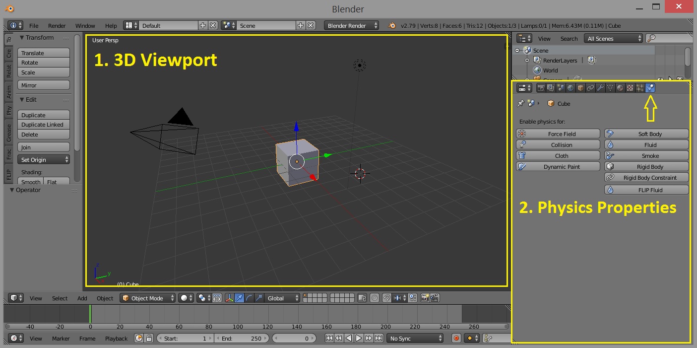
Lets get started! In this guide, we will mainly be focusing on interacting with the following areas of the Blender user interface:
- The 3D Viewport - for selecting and manipulating scene objects
- The Physics Properties Panel - for interacting with the FLIP Fluids simulation settings
First, we will start off with opening a new Blender scene. We will save this scene as my_first_simulation.blend. Saving the Blend file is not necessary, but will ensure we don't lose any simulation progress if we accidentally close the .blend file.
Next, we will create the simulation Domain object. The simulation domain is the volume where the fluid will be simulated. Fluid cannot exist outside of the domain object. The domain object must be cuboid shaped and aligned to the Blender x/y/z axis'.
-
Select the default cube
- We will use this cube as our domain. If your scene does not have a default cube, create a cube and select it.
-
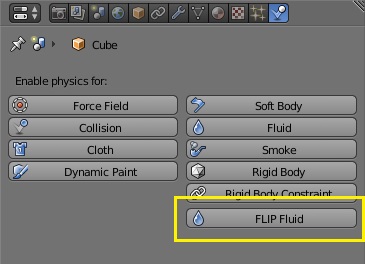
Set this object as a FLIP Fluid object
- In the Physics Properties panel, click the FLIP Fluid button. This will set the selected object as a FLIP Fluid simulation object.
-
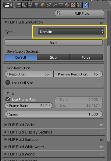
Set FLIP Fluid object type to Domain
- In the Type dropdown list, select Domain. This will activate the object as a domain object. The physics panel will now contain many panels and settings to control the simulation. We will only need to focus on small number of these settings in this guide.
-
Set Domain Size
- We will scale the domain object to the size we want. We will make the domain object a rectangular shape. In this example, we have used a scale of (x = 6, y = 3, z = 2). Inside of the simulator, each Blender unit is considered to be 1 meter wide. The domain object in this example is 12 Blender units long, so the simulation size will be 12 meters long.
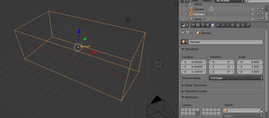
Now we have finished creating our domain object. We will name this object as 'Domain' to keep our scene organized.
Next, we will create an Inflow object. Inflow objects continuously emit fluid into the domain. In this example, our inflow object will be spherical. We'll place the inflow object at one end of the domain and tell it to emit fluid towards the other end.
-
Create an icosphere object
- We will start by creating a new Blender icosphere object that will act as our inflow. We will place the object near the end and close to the top of the domain. In this example we have set the icosphere scale to 0.650.
-
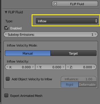
Set the object as a FLIP Fluid Inflow object
- Similarly to how we created the domain, we will select the icosphere object and then click the FLIP Fluid button. This time, instead of setting the type as Domain, we will set the Type to Inflow. The physics panel will now contain settings to configure the inflow object.
-
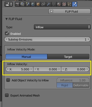
Set the direction of the inflow object
- By default, the inflow will emit fluid and drop it in the direction of gravity. We want to emit fluid towards the other end of the domain and we will do this by setting the Inflow Velocity vector. In our example, the other end of the domain is in the X+ direction, so we will set the X value of the Inflow Velocity vector to 5.0. Inflow velocity values are in units of meters/second.

Now we have finished creating our Inflow object. We will name this object as 'Inflow' to keep our scene organized.
Next, we will create an Obstacle object. Obstacle objects act as solids for the fluid to interact with. In this example, our obstacle object will be spherical dome placed at the domain end opposite to the inflow object.
-
Create an icosphere object
- We will start by creating a new Blender icosphere object that will act as our obstacle. We will want the icosphere to be fairly smooth, so we will set the subdivisions to 4. We will place the object at the end opposite to the inflow. We will position the object so only a bit of the top pokes through the domain floor. This will be our dome. In this example we have set the icosphere scale to 2.0.
-
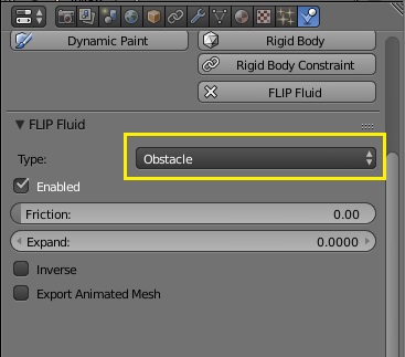
Set the object as a FLIP Fluid Obstacle object
- Similarly to how we created the Inflow, we will select the icosphere object and then click the FLIP Fluid button. This time, instead of setting the type as Inflow, we will set the Type to Obstacle. The physics panel will now contain settings to configure the obstacle object. We will just leave these settings as is.

Now we have finished creating our Obstacle object. We will name this object as 'Obstacle' to keep our scene organized.
Next, we will run our simulation! This process is called 'baking'. The simulator will 'bake' the fluid into an animated sequence of meshes that will become our fluid surface. Depending on how complex and detailed a simulation is, the baking time may range from a few minutes to many hours. The simulation we are running in this guide is simple with a low level of detail, so the baking process should not take longer than a few minutes.
-
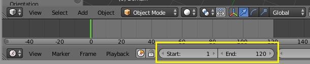
Set the frame range
- The simulator will bake the range of frames that is set in the Blender timeline. We will keep this example simulation short and set the Start value to 1 and the End value to 120.
-
Bake the simulation
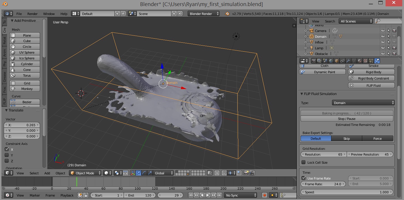
- Select the Domain object to display the domain settings in the physics panel. Click the Bake button to begin baking the simulation.
-
Wait for the simulation to finish baking
- While you are waiting for the simulator to finish baking, you may play/scrub through the timeline to see how the simulation is progressing. The bake button will tell you how many frames have been currently processed.

Congratulations! You have just run your first FLIP Fluids simulation! It's not perfect and doesn't look too impressive, but this is just a simple example and a good start. In the next section, we will look at ways we can improve our simple simulation scene.
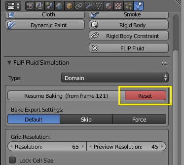
In this section, we will look at ways to improve our simple simulation scene by adjusting a few simulation settings. The settings we will change will require you to reset the simulation and re-bake for the changes to take effect. You can reset the simulation by clicking the Reset button in the domain simulation panel.
Banding artifacts can been seen in the fluid mesh against the obstacle object:

These banding artifacts appear because the mesh generator uses a grid to convert particles to a triangle mesh. When thin layers of fluid are against an obstacle, the particles may not show up well on the meshing grid and may make an appearance as these banding artifacts. There are two simple ways that this can be fixed. The following settings are located in the domain settings under the FLIP Fluid Surface panel.
- Increase particle scale to 1.50 - This will increase particle size when meshing. This will make the particles show up better on the meshing grid. This does not take much more time to compute, but your fluid surface may lose some detail or end up looking 'blobby'.
- Increase surface subdivision level to 1 - This will create a finer mesh grid and generate a higher quality fluid mesh. This will take more time to compute and increase the mesh filesizes.
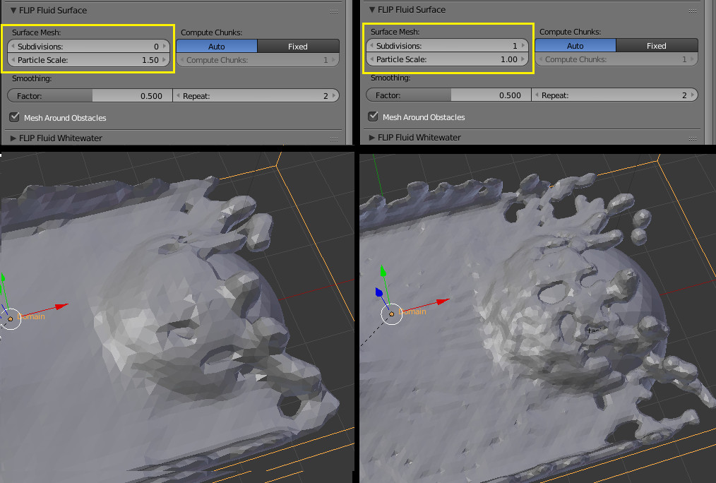
As you can see, the mesh banding artifacts have disappeared! Remember to re-bake the simulation after making either of the above changes to see the effects take place.
Our simple example is quick to compute, but has a low level of detail and does not look very impressive. Increasing the simulation detail can create more interesting and accurate splashes and take your simulation to another level! The amount of detail in your simulation can be controlled by adjusting the simulation Resolution setting. This setting is located in the domain settings under the FLIP Fluid Simulation panel.
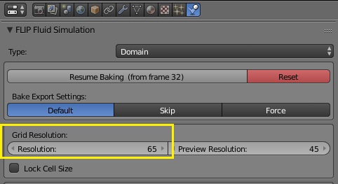
The simulator makes calculations on a 3D grid of voxels. The resolution setting controls how many grid voxels are along the longest side of the domain. The higher the resolution, the higher the number of voxels. Increasing the resolution increases the level of accuracy and detail in the simulation, but will take more time to bake.
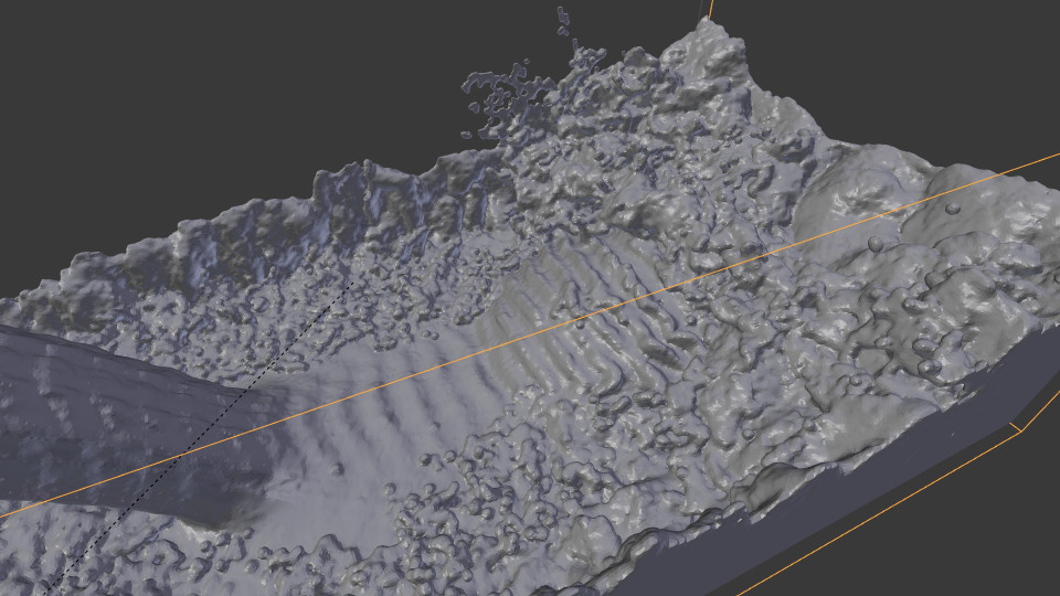
The following image is an example of the fluid with Resolution set to 200 and Surface Subdivision set to 1.
This concludes the guide on creating your first FLIP Fluids simulation! There are many more simulation settings that can be used to customise and fine-tune the look and behaviour of your fluid. With this guide, we have barely scraped the surface! There is much more to learn, so visit the Documentation and Wiki to see more of what the FLIP Fluids addon can do!