This project is an extended work for Laboratorio de Circuitos y Sistemas Electrónicos (LCSE), a subject of Máster Universitario en Ingeniería de Sistemas Electrónicos (MUISE) and Doble Máster en Ingeniería de Telecomunicaciones e Ingeniería de Sistemas Electrónicos (MUIT-MUISE).
The aim of this project is implement a specific use microcontroller with reduced functionalities using VHDL.
The architecture employed is similar to the Harvard's one, and it is shown in the next Figure:
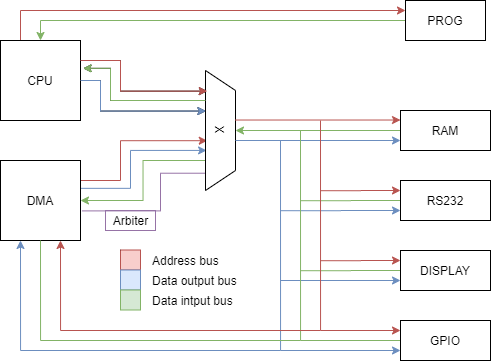
The system is formed by:
- CPU: it is going to be used the PicoBlaze.
- DMA: hardware mechanism that allows data transferring between peripheral and memory in background.
- RS232: serial communication interface.
- Arbitrium signal: allows or denies the access to the master communication bus.
- 7 segment display: shows addresses and its content.
- GPIO: pins for general purpose.
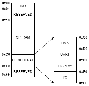
All addresses have been chosen in order to ease the range checking. Thinking in future improvements, some blocks has been left empty.
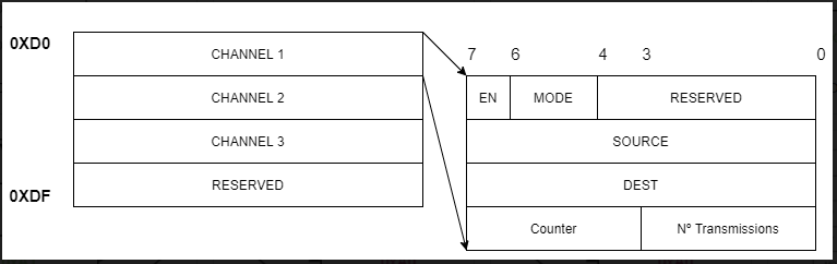
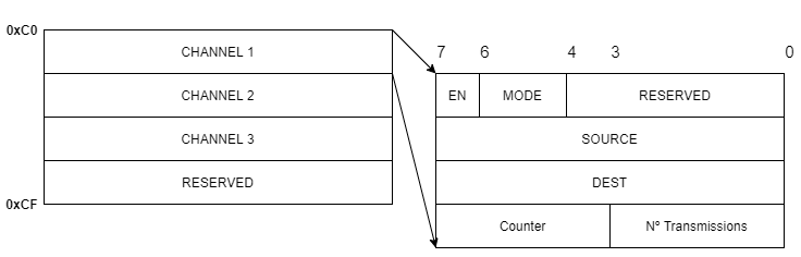
The DMA uses 16 bytes of memory space and its range goes from 0xC0 to 0xD0. Each channel has 4 configuration registers.
- DMA_CONFIG_CH: Most Significant Bit to enable/disable the channel. Next 2 bits to configue the transmission mode:
- 00: Memory to Memory
- 01: Memory to Peripheral
- 10: Peripheral to Memory
- 11: Disabled
- DMA_SRC_CH: source address from 0x00 to 0xFF.
- DMA_DEST_CH: destination address from 0x00 to 0xFF.
- DMA_CNT_CH: The 4 left bits for the transmission counter with values from 0x0 to 0xF. The other 4 bits in the same range for the number of transmissions realizated.
Its memory map is shown below:
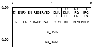
Telecommunication standard designed for serial transmission data. This implementation uses two wires for transmission and reception without flow contro. Its memory map is shown below:
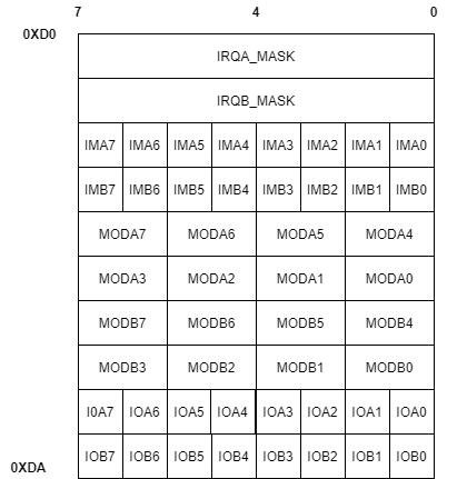
The GPIO uses 10 bytes of memory space and its range goes from 0xE0 to 0xEF.
- IRQ_MASKA/B: Port A/B interruption mask with values from 0X00 to 0XFF.
- IRQ_MODEA/B: Interrupt mode for GPIO 'N'. '1' for falling and '0' for rising.
- MODEA1/2 and MODEB1/2: Funcition mode for GPIO 'N':
- 00: High Z
- 01: Output
- 10: Input
- 11: ALT function
- GPIOA/B REGISTERS: GPIO 'N' value. '1' for High and '0' for Low.
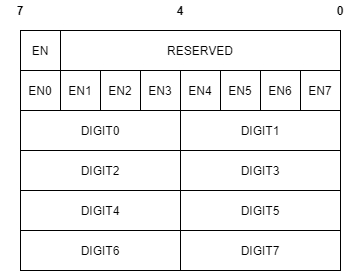
The Segment display uses 6 bytes of memory space and its range goes from 0xD8 to 0xDF.
- EN: MSB for enable or disable the module. '1' for enable and '0' for disable.
- ENX: Enable display X where the MSB is for display 0 and LSB for display 7. '1' for disable and '0' for enable.
- DIGITX_REGISTERS: value of each display. The 4 left bits for pair displays and the other 4 for odd ones.