System information
- OS Platform and Distribution ( Linux Ubuntu 14.04):
- Apollo installed from (source):
- Apollo version (2.5):
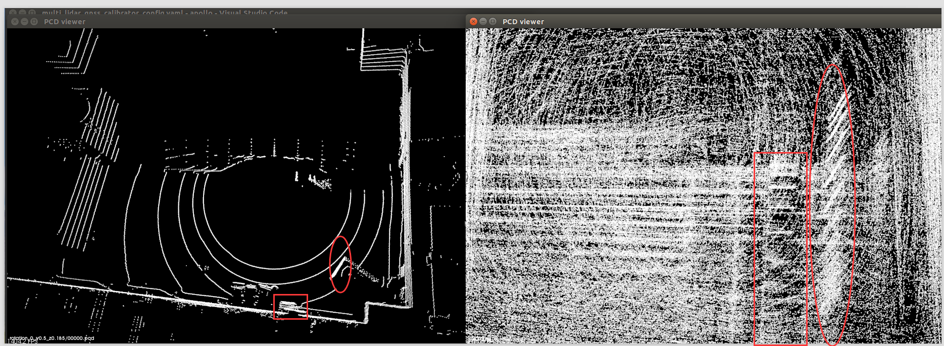
我按照官方的文档说明对激光雷达到GNSS进行校准,但是校准的结果发生了重影的现象,先看校准结果。
I calibrated the lidar to GNSS according to the official documentation, but the calibration results were ghosting, first look at the calibration results.
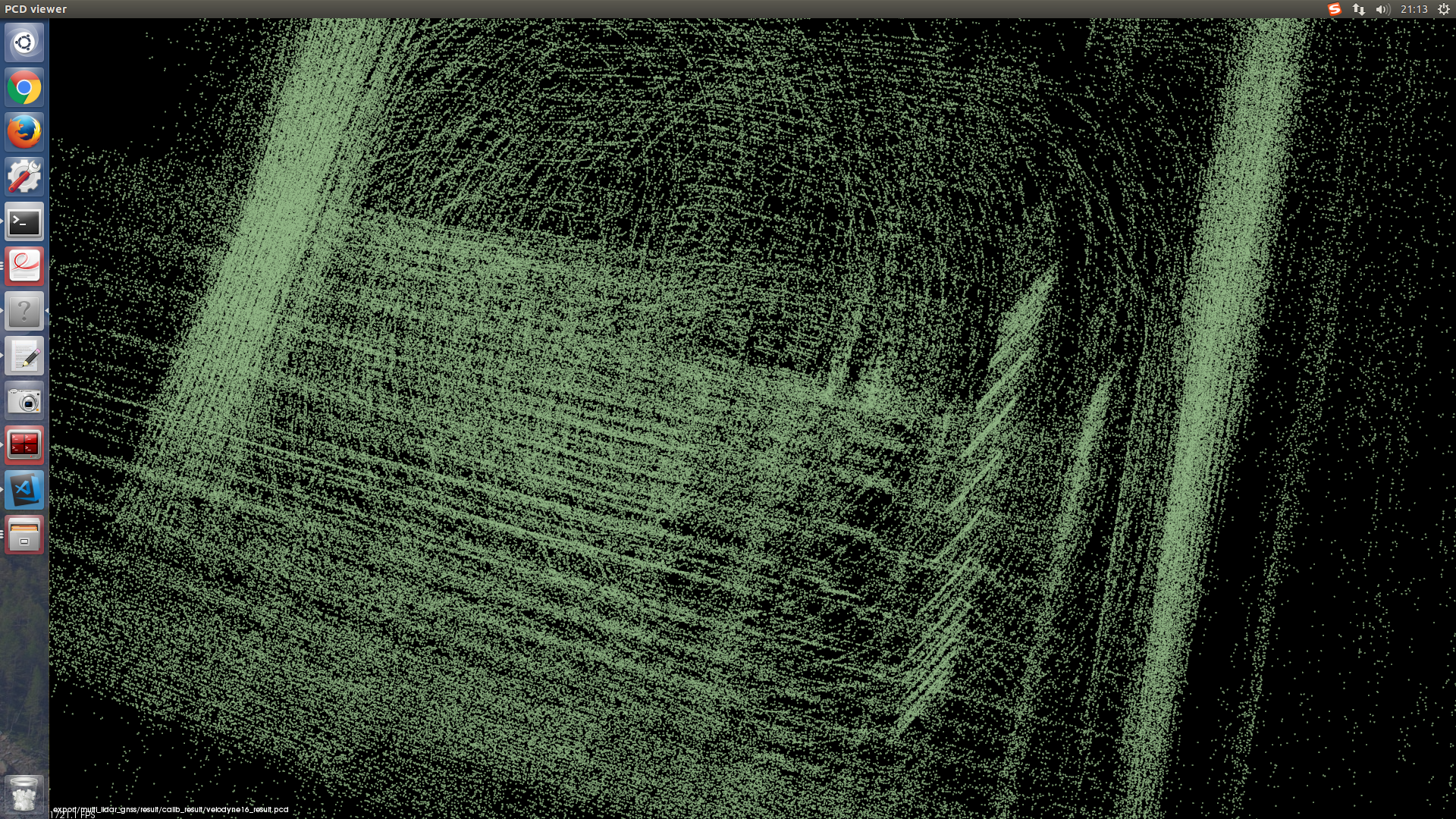
在校准结果的右侧下方是一个物体形成的多个斜线,看起来像是在一个方向上进行多次平移或叠加形成的。如果没有发生这个现象,这个校准结果是正常的。现在我也不知道问题出在哪里了。
Below the right side of the calibration result is a plurality of oblique lines formed by an object, which appear to be formed by multiple translations or superpositions in one direction. If this does not happen, the calibration result is normal. Now I don't know where the problem is.
官方文档和数据。(Official documents and data.)
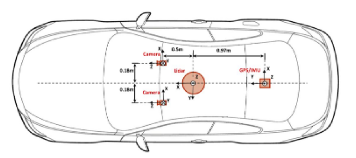
一种典型的传感器安装方式。(A classical installtion of sensors.)
雷达坐标系与系统坐标系示意图。(Lidar coordinate and system coordinate)
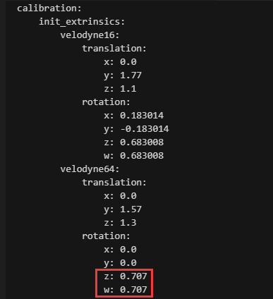
官方64线激光雷达外参(Official apollo platform extrinsics data of Velodyne 64)
我用 欧拉角与四元组在线转换工具知道这是绕z轴旋转90°,如果按照官方的激光雷达安装方式和外参,那最终旋转后的坐标系与GPS/IMU的坐标系的关系图我认为应该是这样的。
I use Euler angle and quad online conversion tool to know that this is rotated 90° around the z axis. If the official lidar installation method and external parameters are used, then after the final rotation The relationship between the coordinate system and the GPS/IMU coordinate system I think should be like this.
                                                              /\ X
                                                              |
                                                              |
                                                              |
                                                              |
lidar                                                GPS/IMU  |
Z(UP)----------------->Y                 Y<-------------------Z(UP)
 |
 |
 |
 |
\/ X
我们的实验平台和外参设置(Our testbed and extrinsics setting)
雷达的坐标系与IMU坐标系示意图(The coordinate figure of lidar and IMU)。
                   /\X                                        /\ X
                   |                                          |
                   |                                          |
                   |                                          |
                   |                                          |
lidar              |                                 GPS/IMU  |
Y<-----------------Z(UP)                 Y<-------------------Z(UP)
雷达、GPS天线、IMU安装位置示意图及距离标注,侧视图(Lidar, GPS antenna, IMU installation location diagram and distance labeling, side view)。
       /\(Z)
        |
        |
Y<------X
                         *****(Lidar)                     ----
                            |                               |
 (Pri ant)                  |                (Sec ant)      |  h=0.185m
    *****                   |                  *****      ----
      |---------0.5m--------|---------0.5m-------|          |
                            |                               |  h=0.335m
                            |-0.105m-|                      |
                                   *****(IMU)             ----
height: lidar - imu 0.52m
Horizontal distance:lidar - imu 0.105m
height: lidar - PriAnt 0.185m
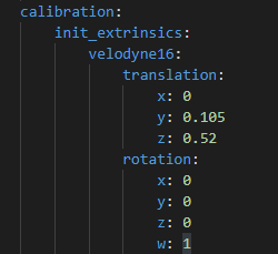
我以为我们在安装雷达时让雷达的坐标系和IMU的坐标系一致,这样在进行校准时就不需要旋转了,于是设置校准外参如下(所有设备的中心都在x轴上,所以平移矩阵中x的值为0)。
I thought that we do not need to do rotation when calibrating if we make the coordinate system of the lidar and the coordinate system of the IMU consistent, so that we set the calibration external parameters as follows(The center of all equipment is on the x-axis, so the value of x in the translation matrix is 0.).
但是结果是这样的(But the result is like this)
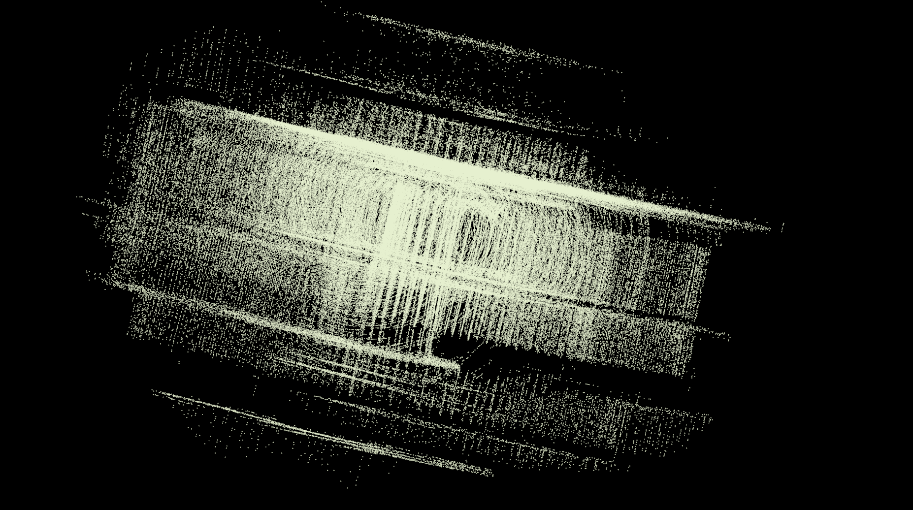
从数据包中提取出来的单个点云图是这样的
(The single point cloud image extracted from the packet is like this)

校准结果与我们的场景非常不符合
(The calibration results are very inconsistent with our scenario)。
于是我又修改了外参如下:
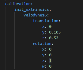
Z = 1 表示绕Z轴旋转180°,这样我们的激光雷达坐标系和IMU的关系也就变成这样了
(Z = 1 means 180° around the Z axis, so the relationship between our lidar coordinate system and IMU becomes like this.)
                                                              /\ X
                                                              |
                                                              |
                                                              |
                                                              |
lidar                                                GPS/IMU  |
Z(UP)----------------->Y                 Y<-------------------Z(UP)
 |
 |
 |
 |
\/ X
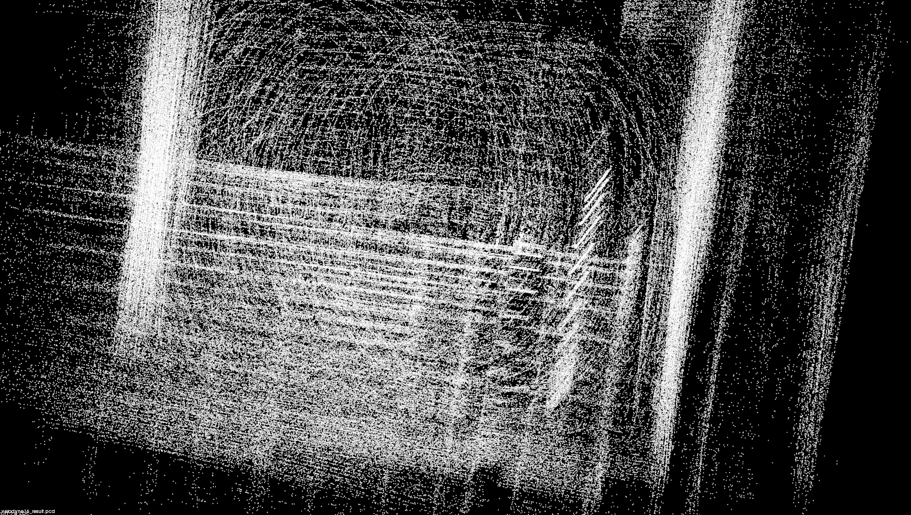
得到了如下结果(I got the following result)
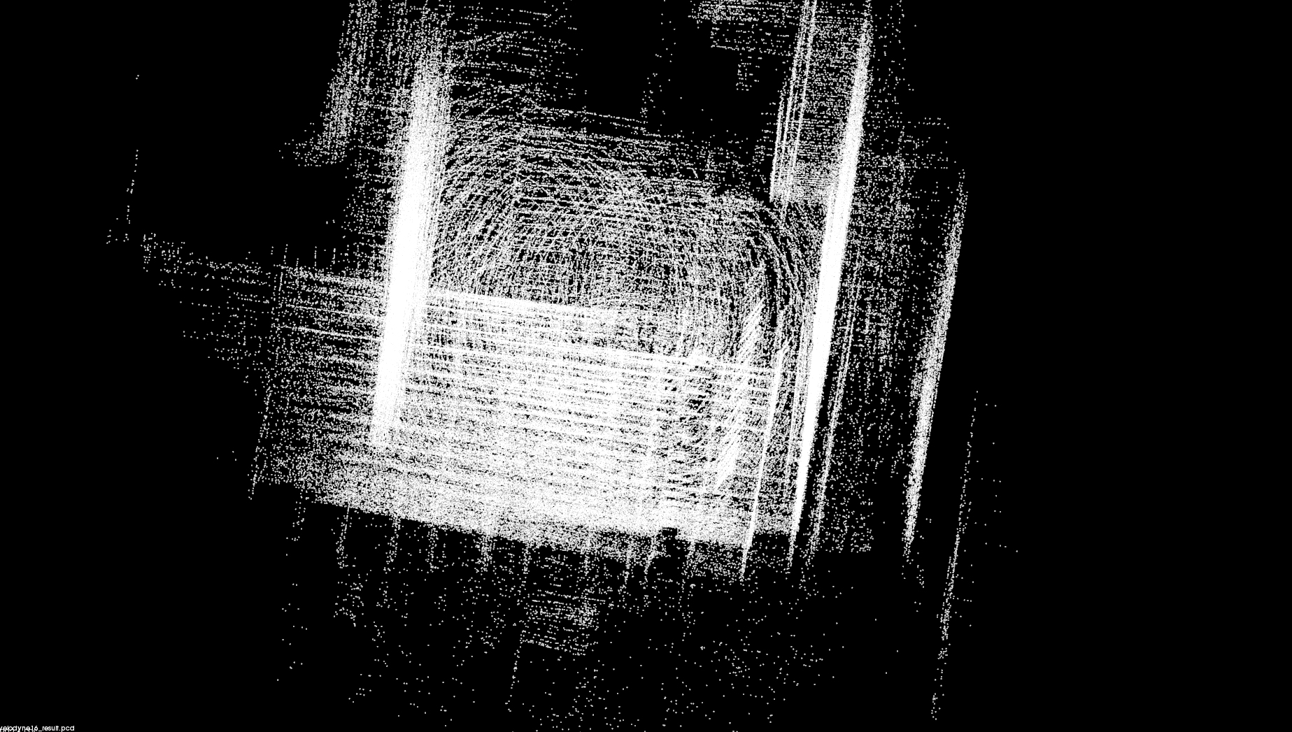
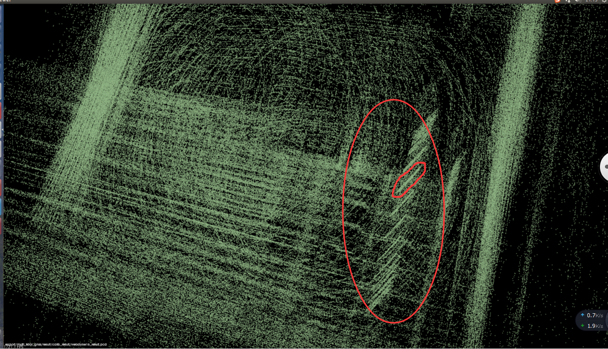
放大一些的图,就像你在开始看到的那样(Magnified image, as you saw it at first)
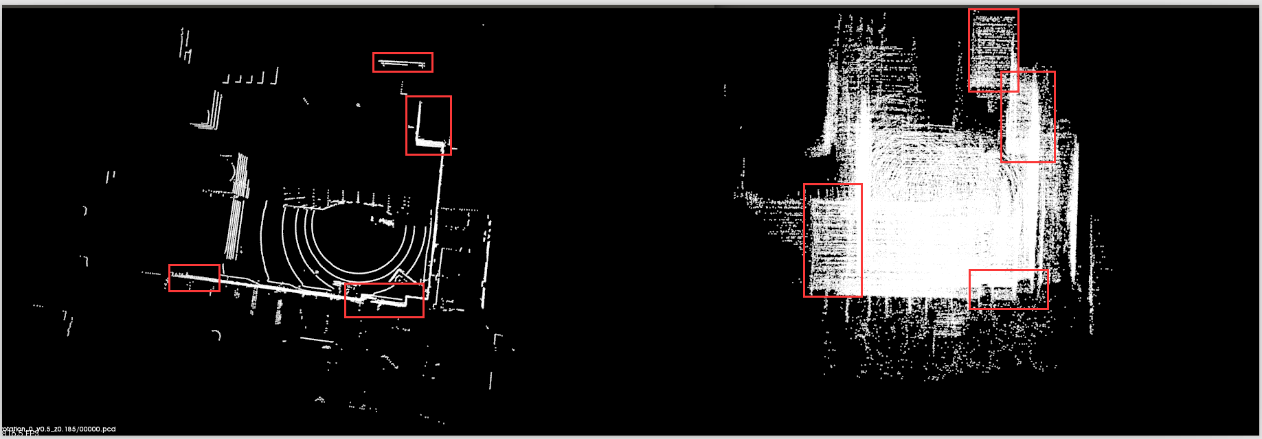
单个点云图与校准结果图对比
(Comparison of single point cloud map and calibration result graph)
看起来这有个平移的问题,但是我不知道外参应该怎么设了。除此之外,我想知道在平移矩阵中的x, y, z表示的是激光雷达到IMU的距离还是激光雷达在IMU坐标系中的坐标。
It seems that this has a translation problem, but I don't know how the external parameters should be set. In addition, I want to know whether x, y, z in the translation matrix represents the distance from the lidar to the IMU or the coordinates of the lidar in the IMU coordinate system.
pcd文件下载:
00000.pcd: 激光雷达原始扫描图(origin pcd file)
velodyne16_result.pcd: z = 1
velodyne16_result_2.pcd: w = 1
pcd.zip
System information
我按照官方的文档说明对激光雷达到GNSS进行校准,但是校准的结果发生了重影的现象,先看校准结果。

I calibrated the lidar to GNSS according to the official documentation, but the calibration results were ghosting, first look at the calibration results.
在校准结果的右侧下方是一个物体形成的多个斜线,看起来像是在一个方向上进行多次平移或叠加形成的。如果没有发生这个现象,这个校准结果是正常的。现在我也不知道问题出在哪里了。

Below the right side of the calibration result is a plurality of oblique lines formed by an object, which appear to be formed by multiple translations or superpositions in one direction. If this does not happen, the calibration result is normal. Now I don't know where the problem is.
官方文档和数据。(Official documents and data.)

一种典型的传感器安装方式。(A classical installtion of sensors.)
雷达坐标系与系统坐标系示意图。(Lidar coordinate and system coordinate)
官方64线激光雷达外参(Official apollo platform extrinsics data of Velodyne 64)

我用 欧拉角与四元组在线转换工具知道这是绕z轴旋转90°,如果按照官方的激光雷达安装方式和外参,那最终旋转后的坐标系与GPS/IMU的坐标系的关系图我认为应该是这样的。
I use Euler angle and quad online conversion tool to know that this is rotated 90° around the z axis. If the official lidar installation method and external parameters are used, then after the final rotation The relationship between the coordinate system and the GPS/IMU coordinate system I think should be like this.
我们的实验平台和外参设置(Our testbed and extrinsics setting)
雷达的坐标系与IMU坐标系示意图(The coordinate figure of lidar and IMU)。
雷达、GPS天线、IMU安装位置示意图及距离标注,侧视图(Lidar, GPS antenna, IMU installation location diagram and distance labeling, side view)。
height: lidar - imu 0.52m

Horizontal distance:lidar - imu 0.105m
height: lidar - PriAnt 0.185m
我以为我们在安装雷达时让雷达的坐标系和IMU的坐标系一致,这样在进行校准时就不需要旋转了,于是设置校准外参如下(所有设备的中心都在x轴上,所以平移矩阵中x的值为0)。
I thought that we do not need to do rotation when calibrating if we make the coordinate system of the lidar and the coordinate system of the IMU consistent, so that we set the calibration external parameters as follows(The center of all equipment is on the x-axis, so the value of x in the translation matrix is 0.).
但是结果是这样的(But the result is like this)

从数据包中提取出来的单个点云图是这样的

(The single point cloud image extracted from the packet is like this)
校准结果与我们的场景非常不符合

(The calibration results are very inconsistent with our scenario)。
于是我又修改了外参如下:
Z = 1 表示绕Z轴旋转180°,这样我们的激光雷达坐标系和IMU的关系也就变成这样了
(Z = 1 means 180° around the Z axis, so the relationship between our lidar coordinate system and IMU becomes like this.)
得到了如下结果(I got the following result)


放大一些的图,就像你在开始看到的那样(Magnified image, as you saw it at first)
单个点云图与校准结果图对比


(Comparison of single point cloud map and calibration result graph)
看起来这有个平移的问题,但是我不知道外参应该怎么设了。除此之外,我想知道在平移矩阵中的x, y, z表示的是激光雷达到IMU的距离还是激光雷达在IMU坐标系中的坐标。
It seems that this has a translation problem, but I don't know how the external parameters should be set. In addition, I want to know whether x, y, z in the translation matrix represents the distance from the lidar to the IMU or the coordinates of the lidar in the IMU coordinate system.
pcd文件下载:
00000.pcd: 激光雷达原始扫描图(origin pcd file)
velodyne16_result.pcd: z = 1
velodyne16_result_2.pcd: w = 1
pcd.zip