Repository navigation
Module and Layout Files
Status: design draft for review. This page proposes how module owners describe their modules and how a FREMO meeting's layout is built from those descriptions, including the routes for a route planner. It replaces the single
module_profile.jsonof Architecture §3.1 with three files. Implemented (2026-10-29): the first part of the node file, as a TOML config file (§4). Implemented (2026-10-30): the module and layout files (schema version 2), their loader and the checks of §8, withhive-rail --check-layout <layout.json>, and an example meeting. Implemented (2026-11-01): modules drawn from SpDrS60 tiles in the module editor, schema version 3 (§11); the example meeting in the repository'sexamples/layout/is drawn that way (two termini, a passing loop over two modules, line modules, a 90° curve, three districts). Schema version 2 below is still read. The workflow of §9 (library, district file, publishing and locking) is design.
Contents
- Why
- Three files, three owners
- The module file
- The node file
- The layout file
- What Hive-Rail derives
- Plan and reality
- Checks
- The meeting, step by step
- Example
- Module editor and schema version 3
- Roadmap
- Open questions
At a FREMO meeting every participant brings modules, and the layout planning team decides how they are put together. Today that plan lives on paper and in CAD drawings; the layout does not know it. Hive-Rail needs the same knowledge to:
- give sensors, points and signals a meaning ("entry sensor of Adorf, west") instead of a bare LocoNet or DCC-EX address;
- find the district borders and with them the transition zones;
- build the topology graph of the whole layout, and from it the routes for the route planner and the timetable;
- show the Zugleiter on the dispatcher screen where trains are.
If every owner describes their modules once, in a file they keep and bring to every meeting, the planning team can load them and the layout is built from them.
| File | Written by | Describes | Changes |
|---|---|---|---|
| Module file | The module owner | One module: its ends, its track, its stations, its devices | When the module is rebuilt |
| Node file | Whoever brings the node (Pi, PC or node board) | The Hive-Rail node: its identity and command station | Rarely |
| Layout file | The layout planning team | One meeting: which modules, which end meets which, which modules form a district under which node | Per meeting |
The module file holds no neighbours and no session, like the profile of the Architecture today: it describes only what the module is. Everything about one meeting is in the layout file.
flowchart LR
    M1["Module files<br/>(owners)"] --> P["Planning team<br/>loads and checks"]
    N1["Node files<br/>(node owners)"] --> P
    P --> L["Layout file<br/>(one meeting)"]
    L --> NA["Every node:<br/>graph, districts,<br/>devices, routes"]
    L --> D["Dispatcher:<br/>map and routes"]
One file per module, named by the module's id, for example timo-adorf-west.json.
{
  "schema_version": 2,
  "module_id": "timo-adorf-west",
  "friendly_name": "Adorf, west end",
  "owner": "Timo",
  "scale": "H0",
  "length_mm": 1200,
  "ends": [
    { "id": "A", "profile": "H0-RE single", "tracks": ["main"] },
    { "id": "B", "profile": "H0-RE single", "tracks": ["main"] }
  ],
  "track": [
    { "id": "t1", "from": "A.main", "to": "W1.trunk", "length_mm": 300 },
    { "id": "t2", "from": "W1.straight", "to": "B.main", "length_mm": 850 },
    { "id": "t3", "from": "W1.diverging", "to": "end", "length_mm": 700 }
  ],
  "turnouts": [
    { "id": "W1", "device": "point_w1" }
  ],
  "stations": [
    {
      "name": "Adorf",
      "code": "Ad",
      "tracks": [
        { "name": "1", "track": "t2", "usable_mm": 800, "platform": true },
        { "name": "Ladegleis", "track": "t3", "usable_mm": 600, "platform": false }
      ]
    }
  ],
  "devices": [
    { "id": "point_w1", "type": "turnout", "bus": "loconet", "address": 12 },
    { "id": "occ_t2", "type": "occupancy", "bus": "loconet", "address": 104, "track": "t2" },
    { "id": "sig_a", "type": "signal", "bus": "dccex", "address": 21, "at": "A.main" },
    { "id": "windmill", "type": "relay", "bus": "board", "address": 40 }
  ]
}-
profileis the FREMO end profile from the norm of the module system, so two ends fit only when their profiles fit. The H0 Europe end boards, for example, come as single-track and double-track variants, and names such as B96, E96 and F96 are used for H0-RE profiles. Hive-Rail only compares names; it does not need the dimensions. The list of accepted names and which of them fit each other is a table in Hive-Rail, kept with the FREMO norms (M-Q1). -
tracksnames the tracks at that end, from left to right as seen standing on the module and looking out of that end. When two ends meet face to face, the left track of one meets the right track of the other. This is what makes a turned double-track module come out right without anyone thinking about it.
The track is a small graph, not a drawing. Each piece of track runs between two points:
- an end track,
A.main; - a turnout leg,
W1.trunk,W1.straightorW1.diverging(a three-way or slip turnout has more legs, M-Q3); -
end, a buffer stop.
length_mm is the track length, which the route planner needs for train lengths and the timetable. On double track, direction gives a track's regular running direction under right-hand running, for example A>B. On the open line (a module without points) it binds: routes run there only in that direction. In a station a train may run against it, to reach a platform or to turn back. A crossing or a more complicated track plan is drawn with the same pieces.
A station (Betriebsstelle) has the name and short code used in the timetable, and its tracks with their usable length and whether they have a platform. A station is one module (decided 2026-11-02, M-Q4): a station, a passing loop, a long bridge, a transition at an unusual place, anything always used in one composition is designed and built as one and is one module file, even when it is split into boxes to transport it (boxes, §11.3). --check-layout reports a station found in two modules. A station track can be a passing siding ("passing": true): a slower train waits there to let a faster one by.
Passing loops. A passing loop on the open line (Überholstelle) is not a station: it has no platforms, and trains do not stop there by timetable. It goes under passing_loops instead of stations, in the same form: a name, and per direction the through track and the passing siding ("passing": true). Trains run straight on along the through track. They take the siding only when the through track is taken, or when a faster train follows close behind; then they wait at the siding's exit signal until it has passed. One entry signal per direction guards both tracks. Like a station, a passing loop may span two modules (as Cdorf in the bench example), but not a district border. The web view shows its name in small italics, with no station label and no station board. A track marked platform in a passing loop is an error.
"passing_loops": [
  { "name": "Cdorf", "code": "Cd", "tracks": [
    { "name": "3", "track": "1", "usable_mm": 800 },
    { "name": "4", "track": "3", "usable_mm": 800, "passing": true }
  ] }
]Every sensor, point, signal, relay and button the module has, each with:
| Field | Meaning |
|---|---|
id |
Name inside the module, used by the track and turnouts |
type |
turnout, signal, sensor, occupancy, relay, button, transponder, light, animation
|
bus |
Where the address lives: dcc (an accessory decoder on the track, programmed to that DCC accessory address), loconet (OPC_INPUT_REP, OPC_SW_REQ, OPC_SW_REP), dccex (DCC-EX's own <Q> sensors and pins) or board (a pin of the node board) |
address |
The address on that bus, as the device is set up or programmed |
block, track + at_mm, at
|
Where it is: an occupancy detector covers a block; a sensor or signal stands on a track at a distance from the track's from end, or at a point such as an end |
role, for
|
For sensors, signals and relays: entry, stop, edge, boundary, transfer_entry or transfer_relay, and the running direction it serves (A>B); a signal stands on the right of the track in its direction |
aspects, functions
|
Optional: a signal's aspects and the DCC addresses or outputs that show them; a light's or animation's outputs |
The bus matters because sensor 104 on LocoNet and sensor 104 in DCC-EX are different things. Accessory decoders on the track (dcc) are addressed through the district's command station, so their addresses share one space per district, whichever throttle or panel sends the command.
A block is a named stretch of track for occupancy and train positions. Electrically it is bounded by rail cuts in its detected rail; the other rail is common:
"blocks": [
  { "id": "adorf_1", "track": "t2", "cuts_mm": [30, 830], "detected_rail": "right", "occupancy": "occ_t2" }
]
cuts_mm are the positions of the two cuts along the track, from its from end; the block's length follows from them. detected_rail is left, right (seen from the track's from end), outer on double track, or both for a transfer block. A block that spans several track pieces or modules lists its pieces and the cut at each end (M-Q8). The route planner and the dispatcher work in blocks.
Optional, for drawing the module and the layout map; a module file without it still works for everything else.
"geometry": {
  "outline": [[0, 0], [1200, 0], [1200, 500], [0, 500]],
  "ends": { "A": { "at": [0, 250], "facing": 180 }, "B": { "at": [1200, 250], "facing": 0 } },
  "points": { "W1": [300, 250] },
  "track": { "t3": [[300, 250], [520, 360], [1000, 360]] },
  "platforms": { "Adorf 1": [[500, 180], [1100, 225]] },
  "devices": { "sig_a": [40, 210], "windmill": [1080, 440] }
}
In schema version 3 there is no geometry: the module is drawn from its SpDrS60 tiles (§11), and the map takes its drawing from them. This is the example station as it is today, Adorf (timo-adorf in examples/layout/), as the module editor shows it:
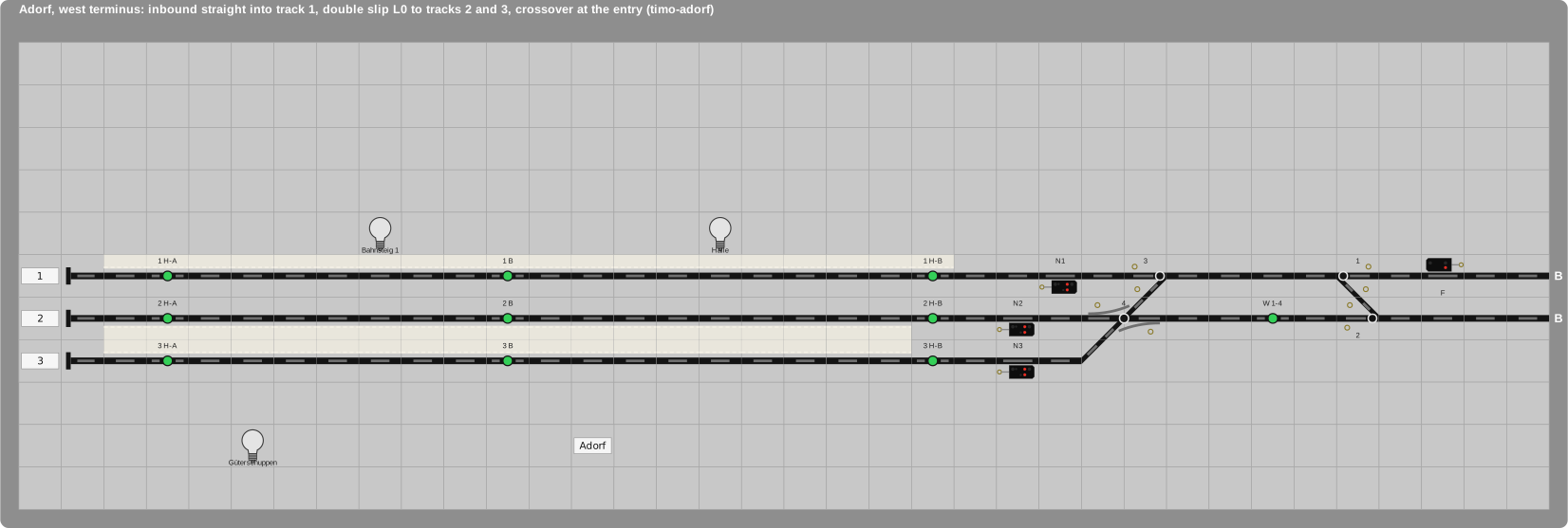
Coordinates are in millimetres on the module, seen from above: x runs from end A towards end B, y from the front edge (the operator's side) towards the back. facing is the direction out of an end, in degrees, 0 along x. Track between two known points is drawn straight unless track gives it a polyline, as for the loading track here. Corner and curved modules are an outline with a different shape and ends that do not face opposite ways. The layout map is built by joining ends: each module is placed so that its end meets the end it is connected to.
A module built as a transition zone declares it at the end where the seam is, with the hardware from Transition Zone §9. The zone is only used when the layout puts a district border at that end.
A plain straight FREMO H0 double-track module with 2E96 end profiles, 900 × 546 mm, as sold as a kit by Pikart Models. A line module like this has no stations and no turnouts; its file is short:
{
  "schema_version": 2,
  "module_id": "fremo-2e96-straight",
  "friendly_name": "Double-track line, straight",
  "scale": "H0",
  "length_mm": 900,
  "ends": [
    { "id": "A", "profile": "2E96", "tracks": ["1", "2"] },
    { "id": "B", "profile": "2E96", "tracks": ["2", "1"] }
  ],
  "track": [
    { "id": "1", "from": "A.1", "to": "B.1", "length_mm": 900, "direction": "A>B" },
    { "id": "2", "from": "A.2", "to": "B.2", "length_mm": 900, "direction": "B>A" }
  ],
  "blocks": [
    { "id": "line_1", "track": "1", "cuts_mm": [20, 880], "detected_rail": "outer", "occupancy": "occ_1" },
    { "id": "line_2", "track": "2", "cuts_mm": [20, 880], "detected_rail": "outer", "occupancy": "occ_2" }
  ],
  "devices": [
    { "id": "occ_1", "type": "occupancy", "bus": "loconet", "address": 201, "block": "line_1" },
    { "id": "occ_2", "type": "occupancy", "bus": "loconet", "address": 202, "block": "line_2" },
    { "id": "in_1", "type": "sensor", "role": "entry", "bus": "loconet", "address": 211, "track": "1", "at_mm": 100, "for": "A>B" },
    { "id": "stop_1", "type": "sensor", "role": "stop", "bus": "loconet", "address": 212, "track": "1", "at_mm": 800, "for": "A>B" },
    { "id": "in_2", "type": "sensor", "role": "entry", "bus": "loconet", "address": 221, "track": "2", "at_mm": 800, "for": "B>A" },
    { "id": "stop_2", "type": "sensor", "role": "stop", "bus": "loconet", "address": 222, "track": "2", "at_mm": 100, "for": "B>A" }
  ],
  "geometry": {
    "outline": [[0, 0], [900, 0], [900, 546], [0, 546]],
    "ends": { "A": { "at": [0, 273], "facing": 180 }, "B": { "at": [900, 273], "facing": 0 } },
    "track": { "1": [[0, 250], [900, 250]], "2": [[0, 296], [900, 296]] }
  }
}
-
Running direction. With right-hand running, a train going from A to B (+x) uses the track on its right, the front track 1; a train from B to A uses the back track 2. In the module's own coordinates this does not depend on how the module is turned, so the module states it per track (
direction). A layout with left-hand running reverses it (M-Q7). -
Blocks and rail cuts. Each block is bounded by two cuts in its detected rail, here the outer rail of each track, 20 mm from the module ends (
cuts_mm, measured along the track from itsfromend). The other rail is common. The block length follows from the cuts: 860 mm. -
Sensors by direction. The entry sensor is where a train arrives, the stop sensor before it leaves the block, so on track 2 they are the other way round from track 1.
at_mmgives the position along the track; the drawing takes x and y from the track's geometry, so a sensor needs no coordinates of its own. - Track order at the ends. The two ends list the same tracks in opposite order: looking out of end A, track 1 is on the left; looking out of end B, track 2 is. Joined to the next module, each track continues on the same side, however the module is turned.
The track spacing of 46 mm is assumed (the prototype's 4.0 m in H0); the FREMO norm gives the real value (M-Q1).
Two such 2E96 modules at the border between the MacBook and Windows districts, with the sensors placed as the takeover specification needs them:

With right-hand running each track has one direction, so each district hosts the transfer block for its incoming track: track 1 (towards Windows) has its transfer block T1 on Windows' first module, track 2 (towards MacBook) has T2 on MacBook's last module. Per direction:
| Item | Where | role |
|---|---|---|
| Source edge block | the last block before the border, on the source side; a declared loco in it starts the handoff | edge |
| Boundary signal | before the border on the source side, on the right of the track |
boundary (signal) |
| Transfer block T | the first block of the receiving district, cut in both rails at both ends, longer than the longest train |
transfer (block) |
| IR beam | across the track at T's entrance, on the receiving node's board | transfer_entry |
| Latching relay | feeds T from the source (RESET) or the receiving district (SET), on the receiving node | transfer_relay |
| Destination entry block | the first block after T; occupied with T clear means committed | entry |
The receiving node switches T to its own feed when the beam at T's entrance has been broken and is restored again for beam_clear_ms (the last car has passed it) and the source edge block is clear. The beam sees the whole train, including cars without resistor wheelsets, and no delay has to be tuned to train length or speed.
In the module file a transfer module marks its block and devices with these roles:
"blocks": [
  { "id": "t1", "track": "1", "cuts_mm": [20, 880], "detected_rail": "both", "role": "transfer", "for": "A>B", "occupancy": "occ_t1" }
],
"devices": [
  { "id": "ir_t1", "type": "sensor", "role": "transfer_entry", "bus": "board", "address": 17, "track": "1", "at_mm": 50, "for": "A>B" },
  { "id": "relay_t1", "type": "relay", "role": "transfer_relay", "bus": "board", "address": 27, "block": "t1" }
]
The layout decides which modules are transfer modules in use: a module is only a transfer zone where the layout puts a district border at its end, and the border check (§8) warns when a border has no transfer block for one of its tracks.
Buildings with lights and level crossings make a module come alive, and the dispatcher and the web view show them. Both refer to devices of §3.4; on the example modules everything is switched over LocoNet:
"buildings": [
  { "id": "station", "name": "Bahnhof Adorf", "lights": ["light_station_hall", "light_station_platform"] }
],
"crossings": [
  {
    "id": "lc", "name": "Feldweg",
    "tracks": [ { "track": "1", "at_mm": 450 }, { "track": "2", "at_mm": 450 } ],
    "lights": "lc_lights", "barriers": "lc_barriers",
    "close": ["lc_close_1", "lc_close_2"], "open": ["lc_open_1", "lc_open_2"]
  }
],
"devices": [
  { "id": "light_station_hall", "type": "light", "bus": "loconet", "address": 101 },
  { "id": "lc_lights", "type": "light", "bus": "loconet", "address": 111 },
  { "id": "lc_barriers", "type": "animation", "bus": "loconet", "address": 112 },
  { "id": "lc_close_1", "type": "sensor", "bus": "loconet", "address": 211, "track": "1", "at_mm": 100, "for": "A>B" },
  { "id": "lc_open_1", "type": "sensor", "bus": "loconet", "address": 212, "track": "1", "at_mm": 600, "for": "A>B" }
]- A building lists the lights in it (devices of type
light). - A level crossing gives where the road crosses each track (
at_mmfrom the track'sfromend), its warning lights (alight) and barriers (ananimation), and the sensors that close it before a train arrives and open it after the train has passed, one pair per track in its running direction. A crossing without a closing sensor gets a warning. - The geometry (§3.6) can draw them:
buildingsgives each building's outline by id,roadsa polyline per road, for example straight across the module at the crossing. - Lights and barriers are LocoNet switch addresses (
OPC_SW_REQ), the crossing sensors LocoNet sensor addresses (OPC_INPUT_REP), so they never clash with each other (§8).
A signal is a device of type signal on a track, facing the trains of one running direction. It guards the exit of its track piece: beyond it begins the next section, up to the next signal.
"devices": [
  { "id": "sig_a1", "type": "signal", "bus": "loconet", "address": 121, "track": "1",  "at_mm": 1080, "for": "A>B", "aspects": ["red", "green"] },
  { "id": "sig_ae", "type": "signal", "bus": "loconet", "address": 125, "track": "2b", "at_mm": 70,   "for": "B>A", "aspects": ["red", "yellow", "green"] }
]-
Aspects. In schema version 3 a signal's aspects are named as in the DB rulebook Ril 301 and come with its tile:
["hp0", "hp1", "hp2", "vr0", "vr1", "vr2"]for an H/V block signal with its distant,ks1,ks2,sh1and so on (see Signal Faces and Choosing and Placing Signals). A signal that can announce a stop (a distant on its mast, or Ks 2) takes two LocoNet switch addresses, its address and the next one, as signal decoders pair them; any other signal takes one. The address check counts both (§8). In schema version 2 the aspects were colours: a two-aspect signal (["red", "green"], thrown is red, closed is green) or a three-aspect signal (["red", "yellow", "green"]); withoutaspects, a signal has two. -
Where.
at_mmis measured from the track'sfromend, like a sensor. The signal stands on the right of the track in its direction, on the platform between two station tracks. Put it on a straight part of the track, before the points it guards. - Routes. A train reserves its way to the next destination one section at a time, all or nothing. A section is reserved only when no other train stands on it or holds it, and its points are set as it is reserved. A train holds at most two signals cleared ahead of it, so it never blocks a station throat it is still far from. Pieces behind the train are released once it has left them.
- Aspect. A signal shows green while a train holds the section beyond it, and red otherwise. It turns red again once the train has passed. A three-aspect signal shows yellow when the next signal on the way is red or the way ends at the destination.
- Stop. A train whose next section is taken halts just before the red signal and waits until the section is free.
The web view draws reserved track in yellow and each signal as its SpDrS60 tile, showing its aspect: stop as Hp 0, proceed as Hp 1 with the distant (or Ks 1) showing what the next signal shows. The simulator does not yet show Hp 2 and Vr 2 for a route over a turnout's curved side. Its header shows the layout's fast clock as the nodes keep it (on the mesh), the real-world time and the time since the simulation started. The simulator (--simulate-layout, --web-sim) works this way. On a layout, the district nodes will set the signals they own over LocoNet.
The transfer block at a district border (§3.7) shows which district feeds it. The sending district feeds it while a train comes in and still stands on the sending side. The receiving district takes over once the train is fully inside and the sending side is clear. The block goes back to the sending district when it is free. The web view gives each district a colour and draws the transfer block in the colour of the district feeding it, named beside it.
Implemented (2026-10-29) as a TOML config file, read with --config <file.toml>. TOML rather than JSON, because the node owner edits this file by hand and needs comments (which Intellibox settings, why the fast clock is off), and TOML has no commas or indentation to get wrong:
mode = "node"
session = "bench"
id = "MacBook"
rocnet-address = 101
dccex = "/dev/cu.usbserial-0001"

[loconet]
tcp = 1234
tcp-slots = "external"
Each key is a command line flag without its dashes, and a table is a flag prefix: tcp = 1234 under [loconet] is --loconet-tcp 1234. true and false switch an option on or off. So every option of the node and the dispatcher works in the file without a schema of its own, and options given on the command line win over the file: one file can serve several nodes (--config bench.toml --id MacBook-2). The repository's examples/config/ holds a reference with every option and its default, and one file each for an Intellibox I, DCC-EX over USB serial, DCC-EX over WiFi and the dispatcher screen.
Still to come, with the module and layout files: a schema version, the session coming from the layout file instead of the node file, and the checksum the layout file keeps of each node file (§5).
The planning team's file for one meeting. It names the module files and node files it was made from, with a checksum each, so a node can tell when an owner brings a changed module.
{
  "schema_version": 2,
  "meeting": "FREMO Bench 2026-11",
  "modules": [
    { "module_id": "timo-adorf-west", "checksum": "8d1f…" },
    { "module_id": "anna-line-1200", "checksum": "02ab…" },
    { "module_id": "bert-bdorf", "checksum": "77c0…" }
  ],
  "connections": [
    { "a": "timo-adorf-west.B", "b": "anna-line-1200.A" },
    { "a": "anna-line-1200.B", "b": "bert-bdorf.A" }
  ],
  "districts": [
    { "node": "MacBook", "modules": ["timo-adorf-west", "anna-line-1200"] },
    { "node": "Windows", "modules": ["bert-bdorf"] }
  ]
}-
connectionspairs module ends. The tracks at the two ends are matched by position (§3.1). -
districtsputs every module under exactly one node and its command station. A district border is every connection between modules of two districts.
From the layout file and the files it names, every node and the dispatcher build the same things:
| Derived | Used for |
|---|---|
| Topology graph of the whole layout: every track piece, turnout and end, joined across modules | Everything below |
| District borders, and on each the transition zone module, if there is one | The handoff (Transition Zone) |
| Routes from every station track to every other: the track pieces, the turnout positions, the total length, the districts crossed | The route planner, the timetable, setting points |
| Device map: bus and address to module, device and meaning, per district | Sensor and point events on the mesh with names, the dispatcher's occupancy view |
| Station list with tracks and usable lengths | The timetable and the dispatcher |
Mesh events then carry the meaning, for example "occupancy timo-adorf-west/occ_t2 occupied" instead of "LocoNet sensor 104 high". Addresses that no module lists still pass between the local LocoNet devices and clients as today, so Rocrail and control panels keep working.
The layout file is a plan. It does not replace Architecture §3.3: a link between two nodes is still only Active when both sides report it. The plan changes how that report is made: instead of picking a neighbour by hand, the operator confirms the link the plan expects, and the node warns when what it sees does not match the plan (a different neighbour, a module that is missing, a module file whose checksum changed). The system never treats the plan as proof that two modules are really joined.
Hive-Rail checks the files when the planning team loads them, so problems are found before the meeting, not on the floor:
| Check | Error or warning |
|---|---|
| Two connected ends have profiles that do not fit | Error |
| Two connected ends have a different number of tracks | Error |
| A module end is in two connections | Error |
| A module is in no district, or in two | Error |
| Two devices in one district use the same bus and address | Error: the devices would answer for each other, for example two signal decoders on the same DCC accessory address. Re-address one, or move a module to another district |
| A district border has no transfer block for one of its tracks (on double track, one on each side) | Warning: a train cannot be handed over there |
| A track piece ends nowhere, or a turnout leg is not connected | Error in the module file |
| A station track is shorter than the trains planned for it | Warning, once the timetable is known |
| A module file changed since the layout was made | Warning on the node |
The address check is the one FREMO meetings feel most: every owner numbers from 1, and LocoNet devices report the address they are set to, so Hive-Rail cannot shift them. Within one district the planning team has to resolve clashes; across districts the same address is fine, because each district has its own bus.
Additions from the implementation:
| Check | Error or warning |
|---|---|
| A district border carries more than single or double track | Error: only standard single or double track may cross between districts. Points, sidings and stations stay inside a district |
| A three-aspect signal | Takes its address and the next one (§3.11); both count in the address check |
| Two LocoNet devices share an address | Only within one address space: LocoNet sensors (OPC_INPUT_REP: occupancy, sensors, buttons, transponders) and LocoNet switches and outputs (OPC_SW_REQ) are separate, so sensor 21 and turnout 21 do not clash |
| A module file changed since the layout was made | The checksum is a 64-bit FNV-1a hash of the file, 16 hex digits; --check-layout prints it for each module. A change check, not a security measure |
| Step | Who | Where | Result |
|---|---|---|---|
| 1. Module library | Every owner | Their own Hive-Rail, at home | A module file for each of their modules, for example ten |
| 2. Sharing | Owners of one district | Email, USB stick, SSH, NFS or SMB (a cloud service later) | Each owner's module files reach the person who brings the district's node |
| 3. District file | Whoever brings the node | Hive-Rail's web view on that node | The modules brought to this meeting, from all owners of the district, in order and orientation |
| 4. To the planning team | The district | Exported as a file and mailed in advance, or published live on the mesh at the meeting | The planning team has every district |
| 5. Layout | The planning team | Their tool: the web view on any node or the dispatcher, or the command line | The districts linked at their borders, checked (§8): the layout file |
| 6. Lock | The planning team | Published on the mesh with a version | Every node loads the same locked layout |
| 7. At the meeting | Every node | — | It builds the graph and announces its district; operators confirm the links the plan expects (§7) |
The planning team works as today: module data comes in before the meeting, and changes on the day are the exception.
Every Hive-Rail keeps a module library: a folder of module files. An owner keeps their own modules there, and imports the files other owners share with them. A module file is complete in itself and its id carries the owner's name (timo-adorf, anna-2e96-border), so files from different owners do not collide. For now files are shared by hand, by email, USB stick or a shared folder over SSH, NFS or SMB; a cloud service may come later.
Several owners usually bring modules into one district, under one node and one command station. The person who brings the node puts the district together from the library, in Hive-Rail's web view:
- choose the modules brought to this meeting, from every owner of the district;
- put them in order and orientation: which end meets which (
timo-adorf.Btotimo-2e96-border.A, or a turned module joined at its other end); - see the checks of §8 that one district can answer already: track graph, addresses within the district, ends that fit.
The result is a district file: the node, the module ids with their checksums, the connections inside the district, and the ends left open towards the neighbours. It is exported as a file to mail before the meeting, or published live on the mesh at the meeting; both carry the same content. The module files go with it, so the planning team has everything.
The planning team imports the district files, links the open ends of neighbouring districts and runs every check. The result is the layout file of §5: its districts and connections are the union of the district files plus the borders.
The planning team locks the layout: it is published on the mesh with a version, and every node loads it. A locked layout is what train tracking and handoffs work on, so it does not change unnoticed during operation. Starting rule (M-Q9): a district may still propose a change, for example a module swapped on the day; the change becomes active only when the planning team approves it and publishes a new locked version.
The lock is a plan, not proof: a link between two districts is still only Active when both nodes report it (§7).
Three modules: the west end of Adorf with its loading track, a plain line module, and Bdorf. Adorf and the line module are in the MacBook district, Bdorf in the Windows district, so the border is between anna-line-1200.B and bert-bdorf.A.
flowchart LR
    subgraph mac["District MacBook"]
        subgraph ad["timo-adorf-west"]
            AA(("A")) --- W1{"W1"}
            W1 -- straight --- AD1["Adorf 1<br/>800 mm"]
            W1 -- diverging --- LG["Ladegleis<br/>600 mm"]
            AD1 --- AB(("B"))
        end
        subgraph ln["anna-line-1200"]
            LA(("A")) --- LT["line<br/>1200 mm"] --- LB(("B"))
        end
    end
    subgraph win["District Windows"]
        subgraph bd["bert-bdorf"]
            BA(("A")) --- BD1["Bdorf 1"]
        end
    end
    AB --- LA
    LB ===|"district border"| BA
Derived routes include "Adorf 1 to Bdorf 1": W1 straight, line, across the MacBook–Windows border; and "Ladegleis to Bdorf 1": W1 diverging, the same way. The border gets a warning unless one of the two modules at it is a transition zone module.
A module is drawn in the module editor of the web view (/panel), as in Rocrail's editor, from square tiles in the style of the Siemens SpDrS60 signal box. The editor opens and saves the module file; that file is the one source of everything about the module, and Hive-Rail derives the rest from its tiles. Owners do not write JSON.
- A module's grid is its real size in cells of 50 mm, rounded to the nearest cell: a 900 × 546 mm 2E96 module is 18 × 11 cells. 50 mm is about the 46 mm between the tracks of H0 double track (NEM 112), so parallel tracks lie one cell apart, and FREMO lengths divide into whole cells.
- The real size counts for planning and for the simulator: a track's length is its share of the module's real length and depth. The screen shows the grid.
- All turns are 45 degrees, as on the real panel: a curve tile turns the track by a quarter, curve tiles in a row make a diagonal.
- Joining rule: track meets a tile edge only at the middle of the edge, always over the same span, so any two tiles placed side by side join flush. Track that meets neither another tile nor the edge is an open end, marked red in the editor and refused by the loader.
Track, curve, left- and right-hand turnout, crossing and double slip (two cells wide), buffer stop, occupancy sensor (a dot in the middle of the track: green free, red occupied), platform track (platform above, below or both, so tracks a row apart make an island platform), level crossing, district border, train number, name plate, lamp, windmill and action tiles, and a tile for every DB light signal sold for H0 with LEDs (Viessmann): H/V block, entry and departure signal, each also with its distant signal below on the same mast, H/V distant, Ks main, Ks multi-section, Ks distant and the light shunting signal. A signal tile shows the signal small, lying along the track on the right of it, with its lamps where the model has them; its aspects are named as in Ril 301 (Hp 0, Hp 1, Hp 2, Vr 0–2, Ks 1, Ks 2, Sh 0, Sh 1); Sh 1 on Ks signals, the upper white and Hp 0 with one red are options. See Signal Faces. The tiles are Hive-Rail's own drawings (assets/spdrs60/, assets/signals/).
{
  "schema_version": 3,
  "module_id": "timo-adorf",
  "friendly_name": "Adorf",
  "owner": "Timo",
  "scale": "H0",
  "size_mm": [1800, 546],
  "ends": [ { "id": "B", "side": "right", "profile": "2E96", "tracks": ["in", "out"] } ],
  "tracks": [ { "name": "in", "direction": "B>A" } ],
  "tiles": [
    { "tile": "turnout-left", "x": 26, "y": 5, "turn": 2, "id": "3", "block": "throat", "device": "point_3" },
    { "tile": "signal-hv-departure", "x": 24, "y": 5, "id": "N1", "track": "1", "block": "adorf_1_e",
      "device": "signal_n1" },
    { "tile": "sensor", "x": 21, "y": 5, "id": "1 H-B", "track": "1", "block": "adorf_1_e", "device": "sensor_1_h_b" }
  ],
  "stations": [ { "name": "Adorf", "code": "Ad", "tracks": [ { "name": "1", "track": "1", "platform": true } ] } ],
  "blocks": [ { "id": "adorf_1_e", "track": "1", "detected_rail": "outer",
                "sections": [ { "device": "sensor_1_h_b", "role": "stop", "for": "A>B" } ] } ],
  "devices": [ { "id": "signal_n1", "type": "signal", "bus": "loconet", "address": 121,
                 "decoder": "Viessmann 5229", "aspects": ["hp0", "hp1", "hp2"] } ]
}-
Tiles: place (
x,y),turn(0 to 3 quarters clockwise),mirror(flipped across the track, before turning), and what the tile stands for:id(a turnout's number, a signal's or sensor's name),track(the track it belongs to),block(its occupancy section),device,text,options(a signal's lamps, a track's platforms),distant(the signal a distant signal announces). - Ends are found where track leaves the grid; each gets a name and an end profile, and its tracks follow from the tiles. A terminus whose platform tracks end at buffer stops has one end; its back side is named for directions ("B>A": towards the buffer stops).
- Devices keep their bus, address and decoder; a tile only names its device.
-
Blocks: each occupancy section is a block, drawn on its tiles, with its sensor;
roleisstop,brake,throat, or at a district bordertransfer,edgeorentry.
Boxes. A module that is one composition but too long to carry (a station, a passing loop, a long bridge) lists the boxes it is built of, from end A, so that layout planning knows the real pieces and the editor and the map show where they meet (a dashed line; no turnout or signal on a joint):
"boxes": [
  { "id": "west", "length_mm": 1200 },
  { "id": "east", "length_mm": 1200 }
]
Together they must be the module's length (--check-layout). The example's Cdorf is one module of two boxes of 1200 mm (examples/layout/timo-cdorf.json).
The track pieces between turnouts, buffer stops and module ends, with their lengths; turnouts (a double slip as two halves, 4a and 4b); each signal's and sensor's track, place and direction (a signal faces the way its tile faces); each block's extent; stations' usable lengths; the map, drawn from the tiles and placed by joining the module ends, its lamps following the layout.
- Signals: entry signals A (in the direction of rising kilometres) and F; exit signals N and P with the track number (N1, P2); block signals numbered, odd and even by direction; a distant signal named after the signal it announces, in lowercase (a, f, n3).
- Turnouts: numbered per station from its entry in kilometre direction; a crossover is a pair (1/2), a double slip's halves a and b (4a/4b).
- Occupancy sections: by track and kind: H a stop section with the end it lies at (1 H-A), B a braking section, S the open line, T a transfer section and R an edge section at a district border; a station throat W with its turnouts (W 1-4).
- Level crossings: BÜ with their name; their switch-on and switch-off contacts ESK and ASK.
A station track has three occupancy sections: a short stop section at each platform end (up to the exit signal or the buffer stop) and the braking section between them; a station throat has a section of its own; a passing loop track (run one way) a braking and a stop section; the open line one section per track and module.
| Step | Roadmap |
|---|---|
Node file as a TOML config file (--config) |
1.7, done |
| Module, node and layout file schemas (version 2), loader and checks, with the current version 1 profile still read | 1.1 to 1.3: module and layout files, loader and checks done (--check-layout) |
| Module library, district file (export and import), publishing and locking on the mesh (§9) | new |
| Binding confirmation against the plan | 1.4 |
| Topology graph and routes | 1.5 |
| Device map: LocoNet and DCC-EX sensors and points on the mesh with names | new |
| Dispatcher map and occupancy view | 7.6: the web view, on the layout simulator so far |
| Graphical module editor | done (2026-11-01): /panel, modules drawn from SpDrS60 tiles, schema version 3 (§11) |
| Transition zones at the derived district borders | 5.x |
| # | Question | How it will be answered |
|---|---|---|
| M-Q1 | Which FREMO end profile names exist per module system, and which fit each other? | From the FREMO norms per module system; a table in Hive-Rail |
| M-Q2 | Do FREMO groups already keep module data in a format Hive-Rail could import? FREMO:87, for example, keeps a module database and plans arrangements from checked CAD drawings | Ask the planning teams |
| M-Q3 | How are three-way turnouts, double slips and crossings described: more legs, or a small graph of their own? | First real modules |
| M-Q4 | Is joining a station across modules by name enough, or does a station need its own file? |
Answered (2026-11-02): a station is one module, one file, however many boxes it is built of (§3.3, boxes in §11.3) |
| M-Q5 | How does the layout file reach the nodes at the meeting: copied by hand, or shared on the mesh with a version? | Answered (§9): district files by file before the meeting or live on the mesh; the locked layout published on the mesh with a version |
| M-Q9 | Locked layout: no edits at all, or proposals that become active once the planning team approves them? | Starting rule: proposals with approval (§9.4); decide with the first meetings |
| M-Q6 | Besides block cuts, does the module file describe other electrical sections, for example a separately fed station or a reverse loop? | Booster and occupancy tests |
| M-Q7 | Do FREMO meetings ever run left-hand (some prototypes, such as France, run left)? Then the layout file sets the running side and the module's direction is reversed |
Ask the planning teams |
| M-Q8 | Should a block always be cut at module ends, or may it span modules with the cut on a neighbouring module? | First multi-module blocks |