This list will allow you to complete a working FM Radio Receiver using the Raspberry PI 3b+ in conjunction with a TEA5767 I2C device.
Ill start by listing the required components, where to buy them, how to design then assemble those components, then finalize with testing the device in an appropriate enviroment.
This project was completed over a 15-week semester, however with these steps, a working prototype could be completed in a week from purchasing components to hearing music on the receiver.
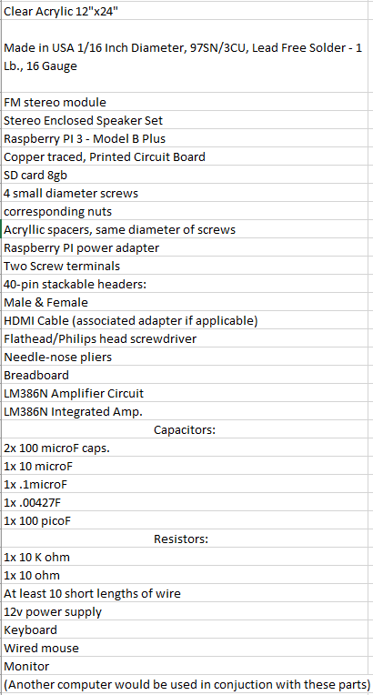
Heres a list of all parts needed to complete this project.
Youre budget will vary from mine, as I had a number of components and tools and access to a prototyping lab which greatly decreased my overhead costs. I also had to buy additional components that were not originally on the budget or parts list files that I have uploaded HERE on my repository. As well, my major mistake of frying a Raspberry PI (which could set you back another $50.00) wasn't included in the budget. The amplifier originally was planned to be the Class-D amp supplied by buyapi.ca, however I had to put togther the LM386 due to time contraints. However, looking back, this would be a better option; thats why I left it on the final parts list. My total budget by the end of the project was $122.68CAD. I had intitially proposed a $108 total budget.
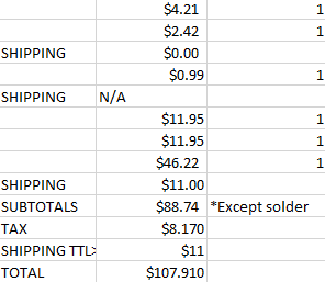
Here is the updated budget These are the costs to be expected, at least at a minimum. This was the first attempt at wrangling up some of these cheap sensors. I went for the cheapest option, and they never arrived.
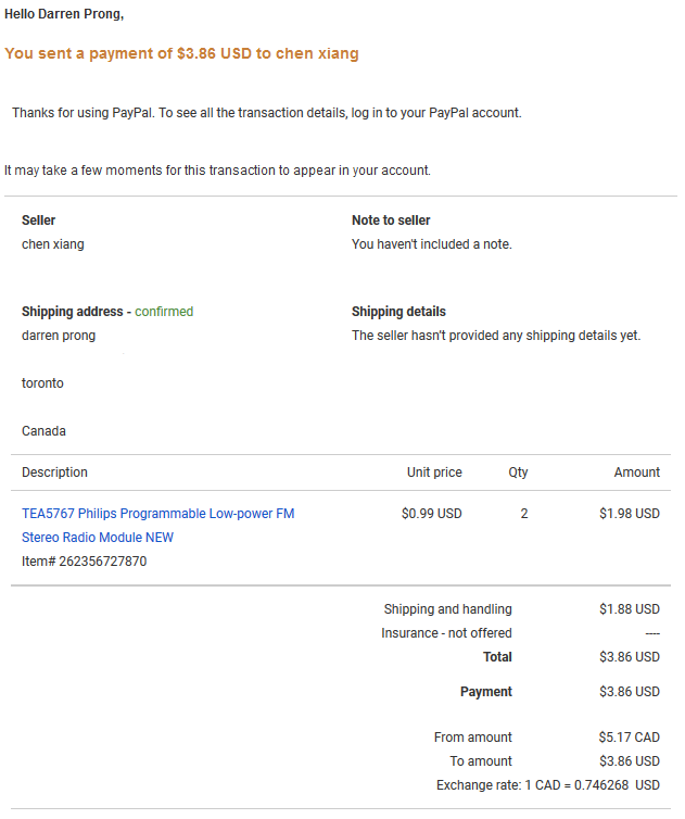
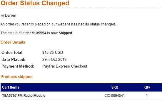
Therefore, go for the one that works, and is quick. I bought the back up at oddwires.com for $15.25 USD:
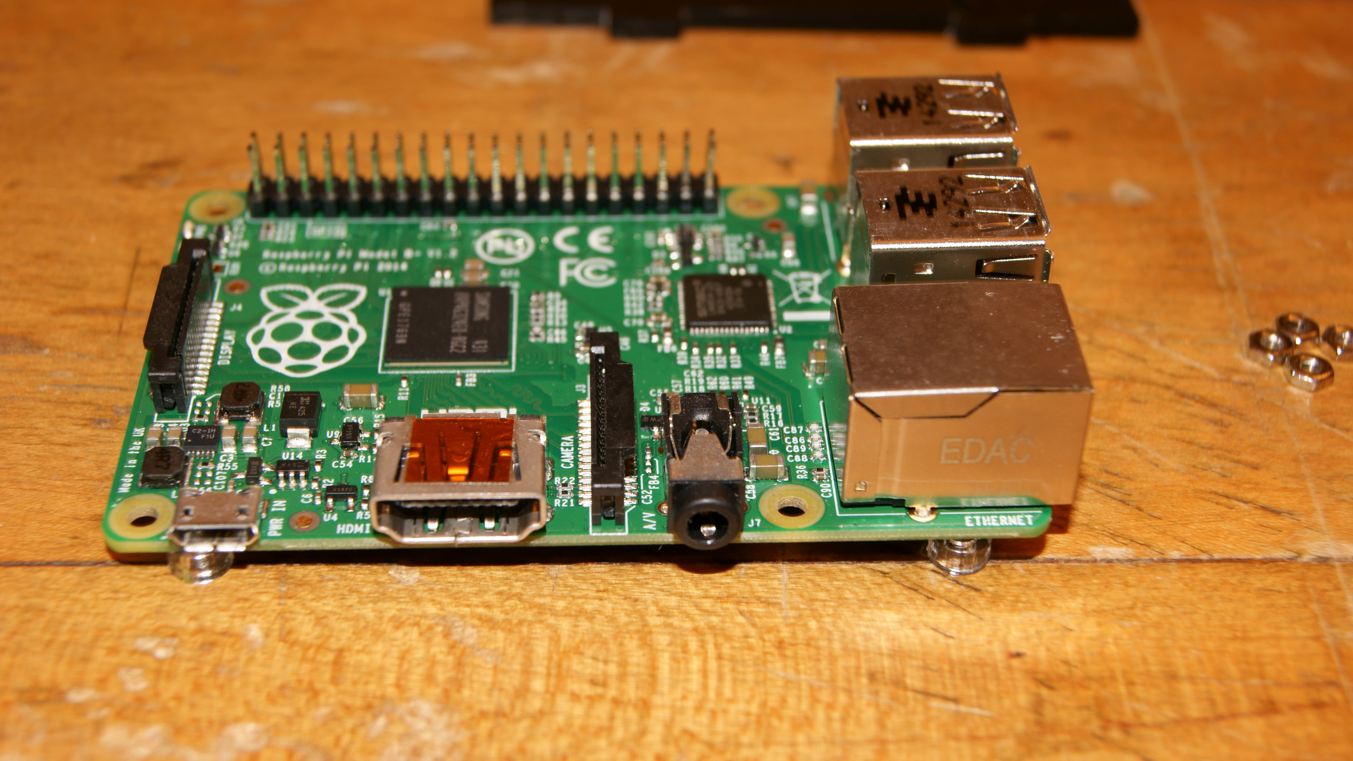
The Pi 3B+ is also my choice for which version to go with.
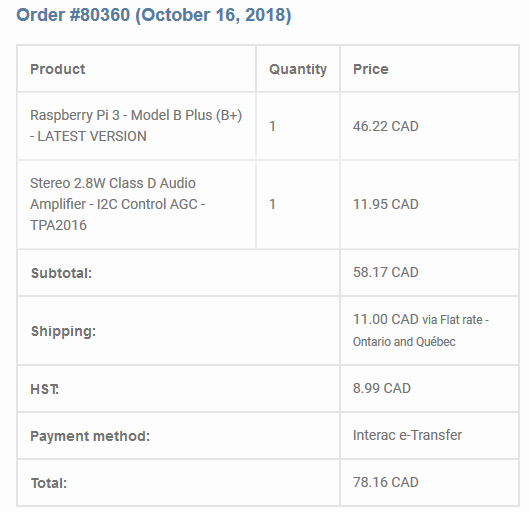
Its the same price as the other Pi's but if you already have the associated pieces for assembly, no need to order a whole parts kit.
Again, these prices are location dependent, as your geographical situation could greatly increase shipping costs or parts availablity. As well, in our prototyping lab, we have access to a $20,000 laser cutter, a lot of spare components and tools, the expertise of professionals, and a great deal more time.
Designing this next two major parts will require some trial and error if you haven't used these programs before. Also, if you've ordered your parts and awaiting the sensor in the mail, this can be done in the interim. To design the device PCB I used the freeware "Fritzing" (which is in BETA at the time of this publication.)
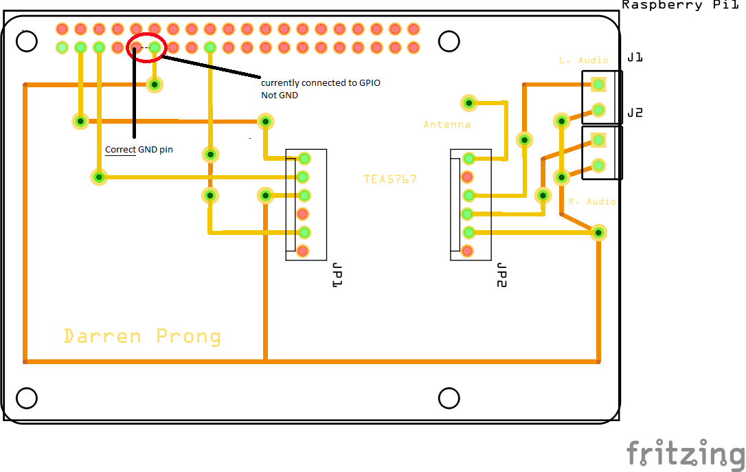
This files could still use some tweaking, and maybe some personal customization; however, this is the simplest design I could create and good for a beginner to learn the basics.
And for the enclosure, CorelDRAW was used on a free 15-day trial as well as access to the program in our lab. The enclosure on CorelDRAW:
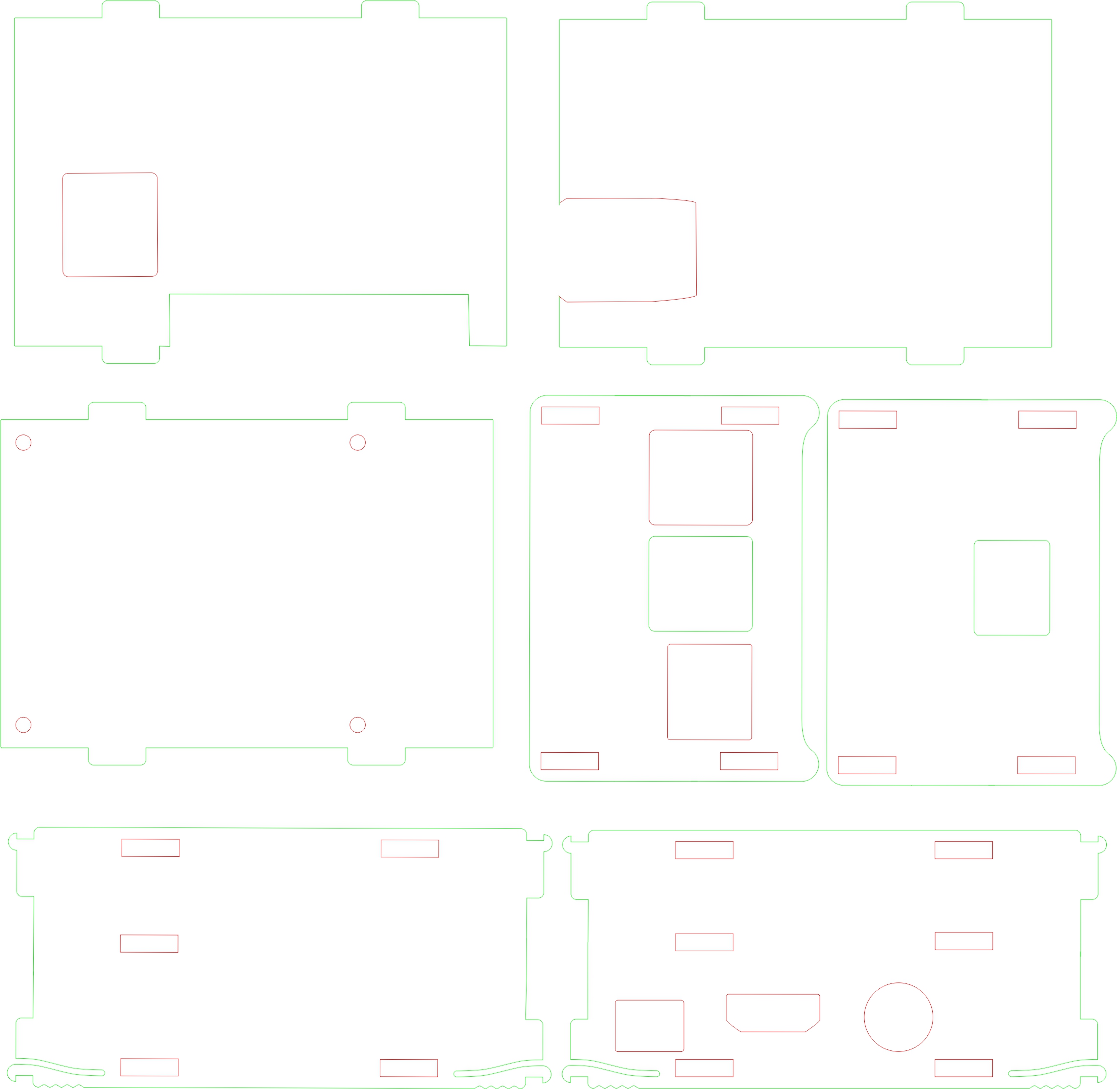
After these are designed, you can send the fritzing file away to be printed. The enclosure was printed a few times, with minor changes for each new job. Its still not a perfect fit, but the file you have here Enclosure will work but the fit is tight, and the middle plate is under pressure from the USB ports pressing from underneath causing it to bend slightly.
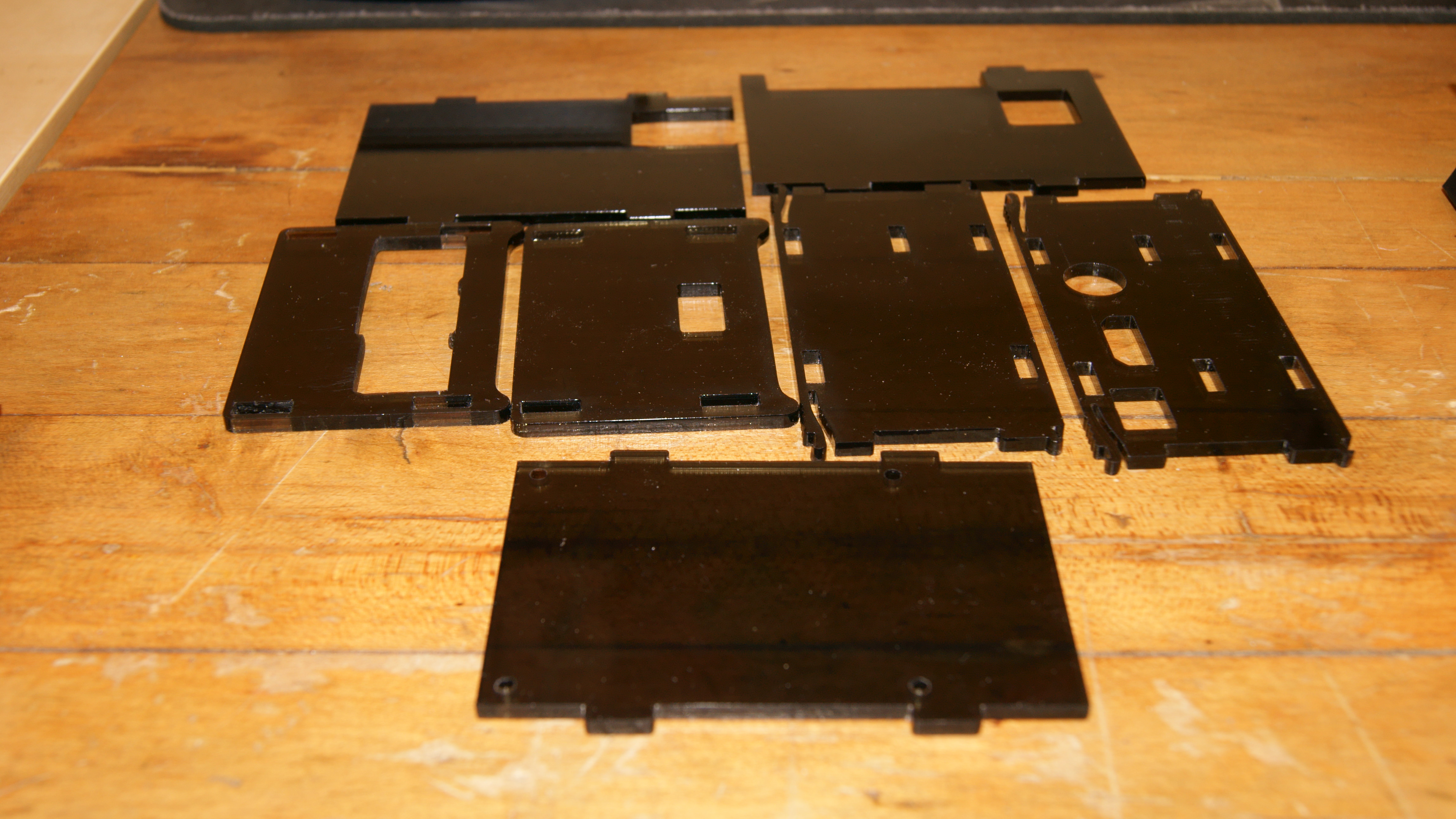
I had to remove the I/O spacing bars, and file down the cutouts for my design, however the design .cdr file included in this repository, won't have this missalignment.
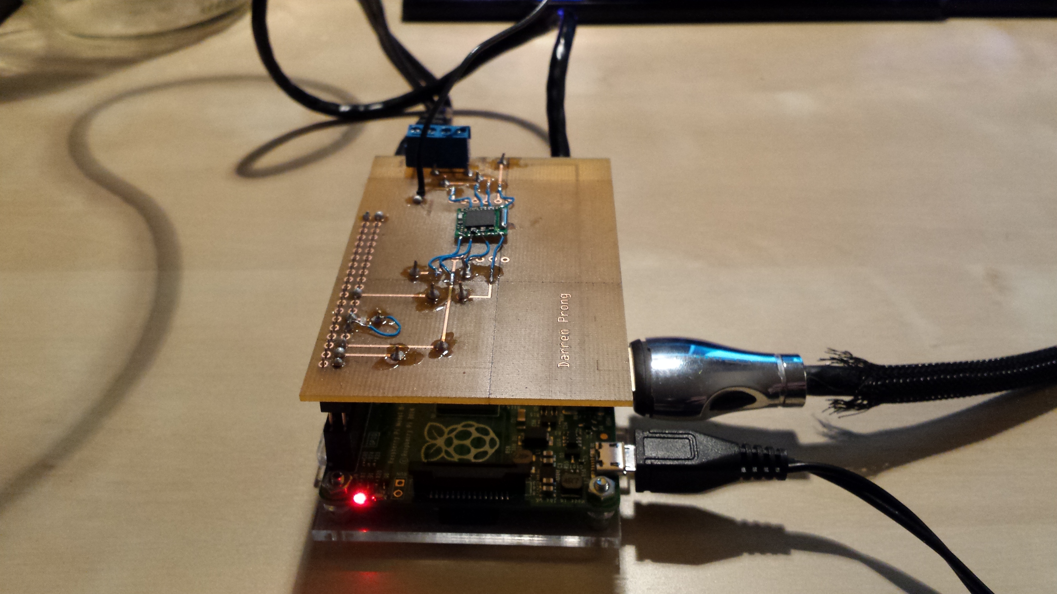
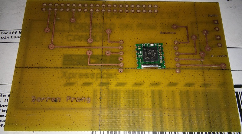
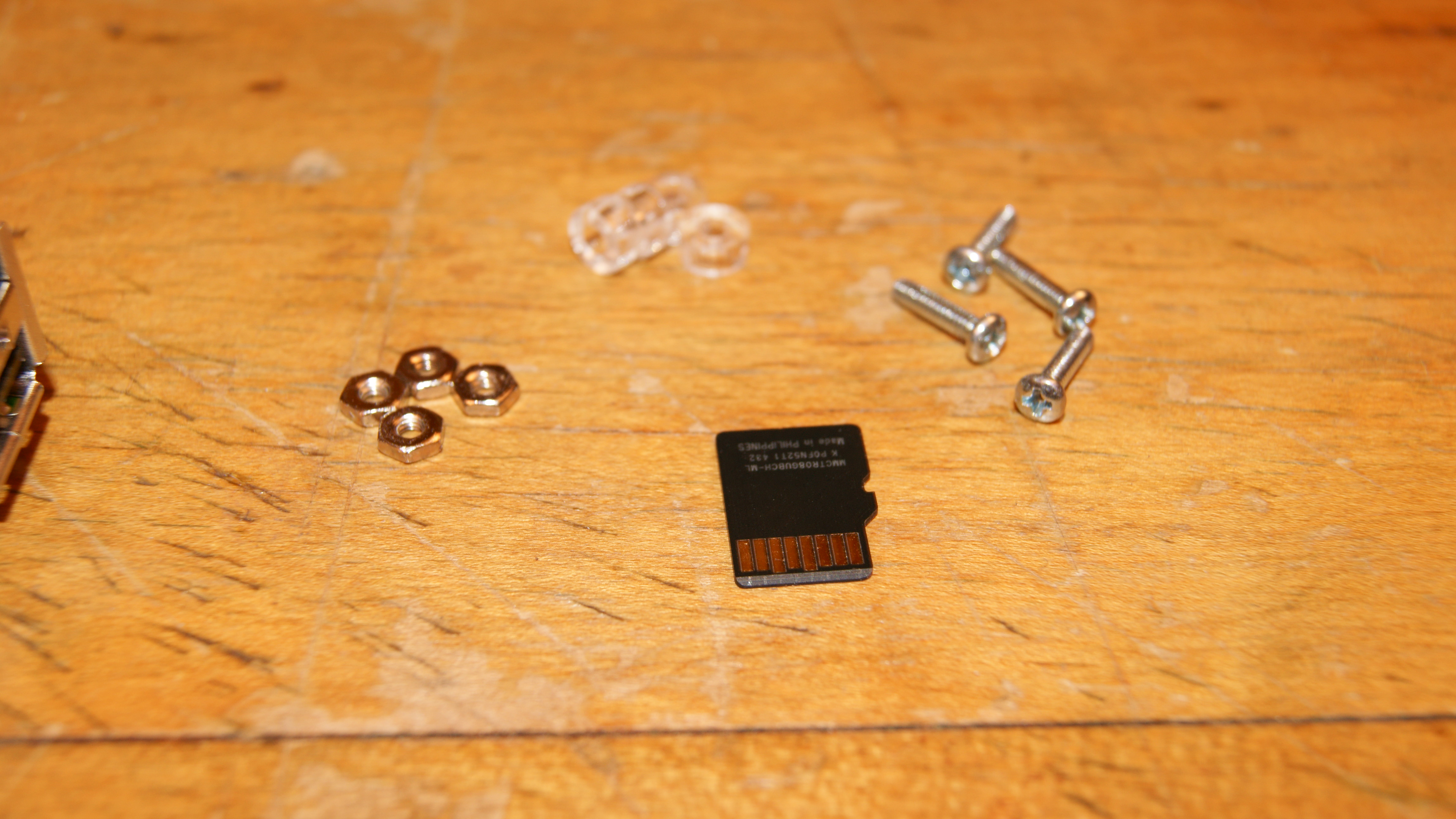
Once the parts are in hand, the design files printed and assembled, Heres what you should have in hand: ...
Start by attaching the the sensor to the PCB, I used hotglue.
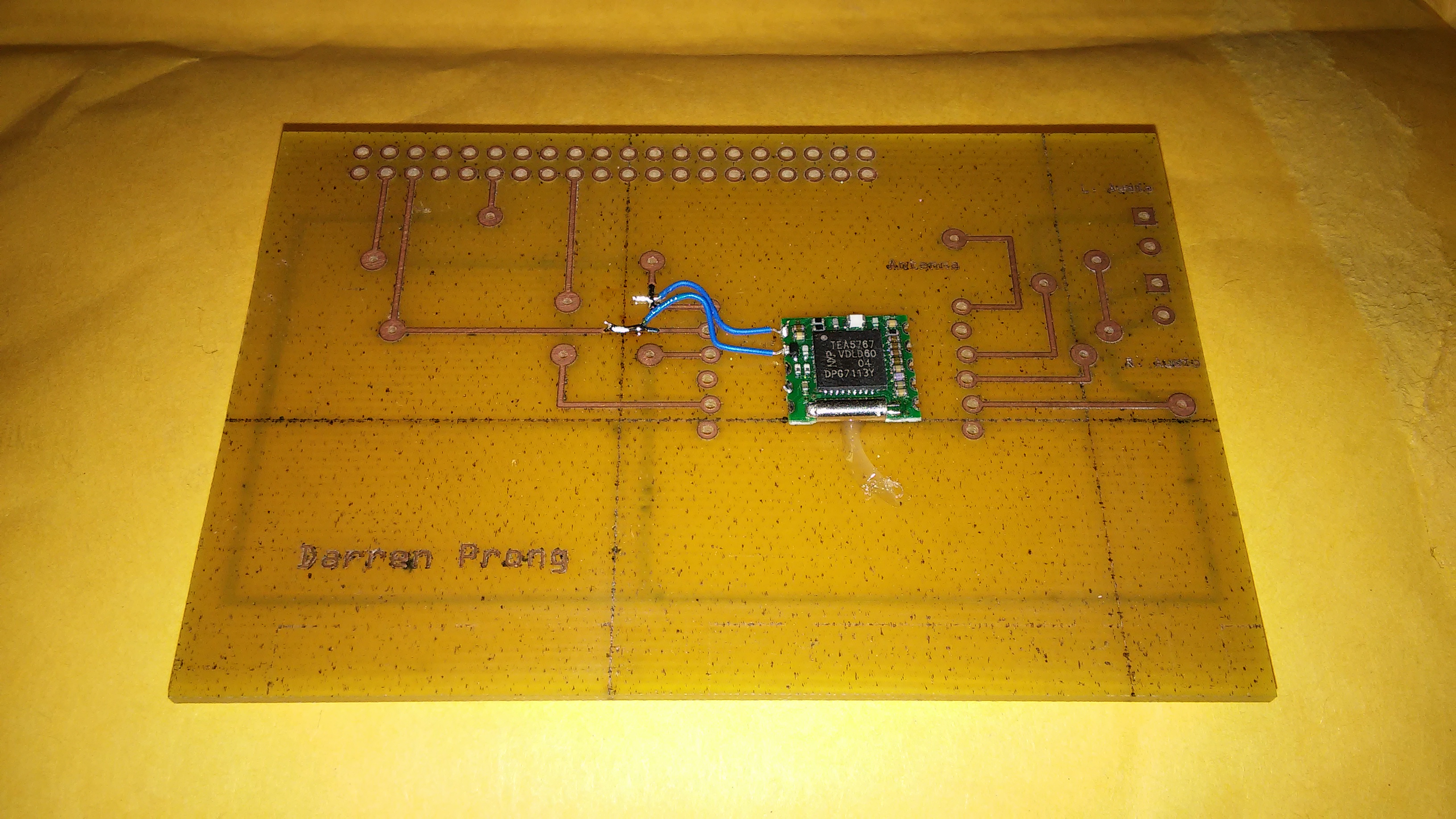
Next step will be to solder a jumper wire from each terminal on the sensor to the corresponding trace on the PCB.
Next will be to solder the via's. I recommend that you take a small amount of 20gauge wire(1cm in length) strip only one end and then insert into all the via's. This will hold it inside the via briefly while you solder the flip side. Solder the entire side with exposed wire first, then flip, remove the insulation, and solder that side for each via.
Double check the shape of each via and how the solder "flows" from the wire onto the copper pad. This ensures a solid connection. It should appear like a sloping hill, or a "Hershey Kiss".
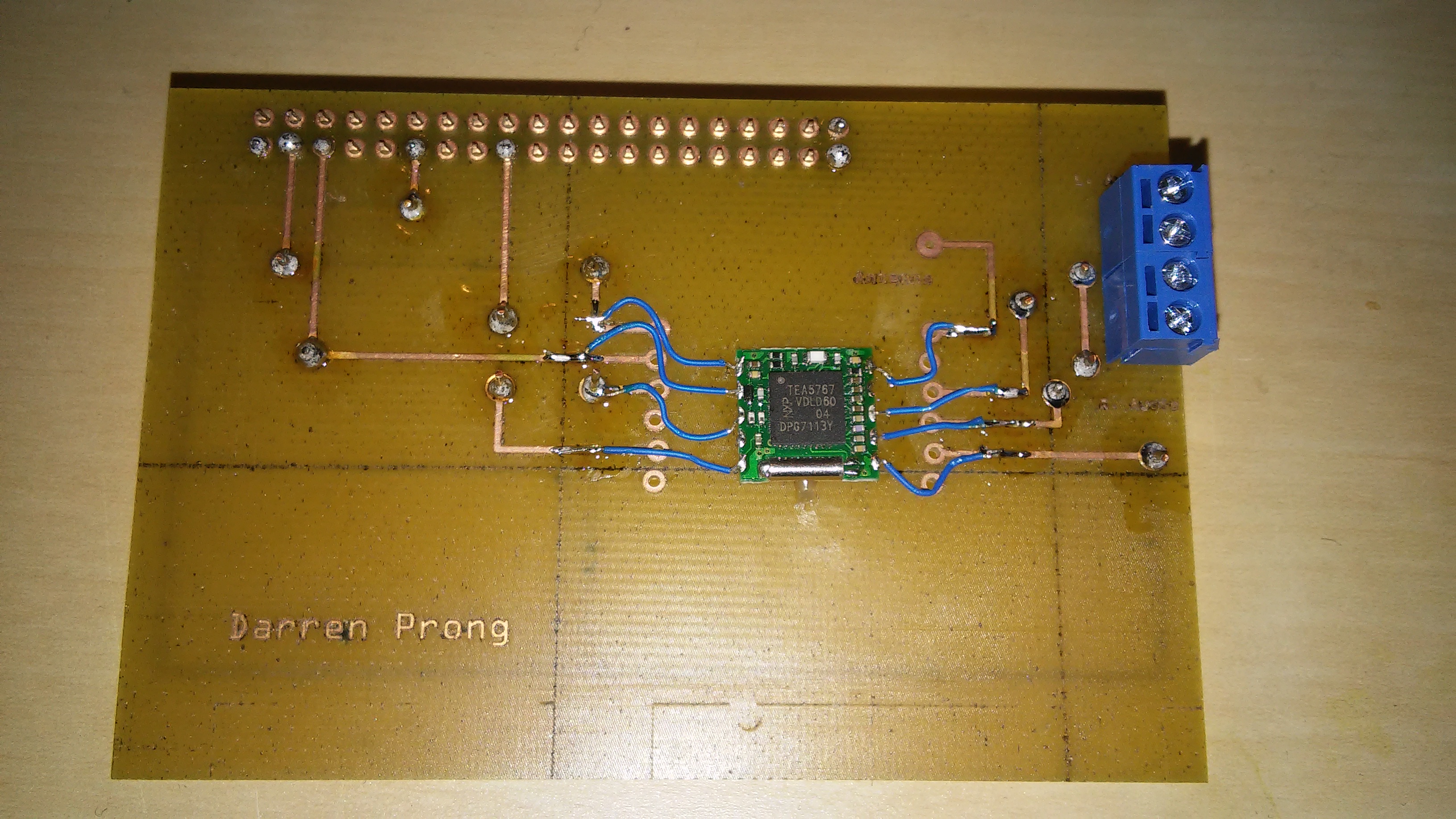
Next, the 40-pin stackable header, along with the two screw terminals to be used with your speakers.
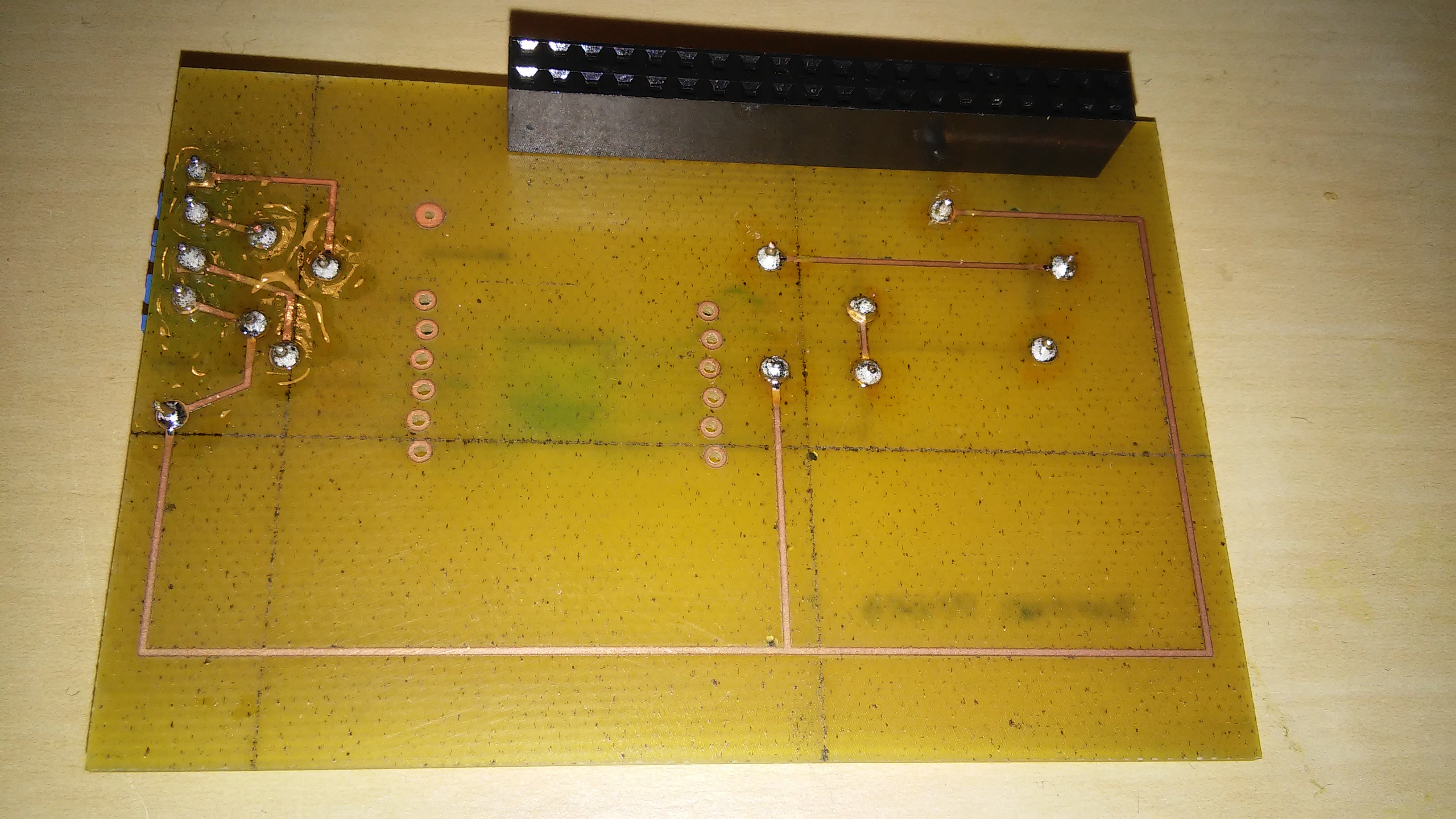
Soldering all 40pins isn't necessary, I only soldered the pins I was using, and two on the far end of the header.
I also left my male 40-pin header plugged in, so I didnt lose it. However, you'll notice it doesn't rest flush up agaisnt the the female header. This could potentially damage both headers as well as the device.
Best practice would be to disconnect from the PI each time your completed testing.
You can now solder on a length of wire (up to you how long) to act as the antenna. Solder this in a similar way as you did with the via's.
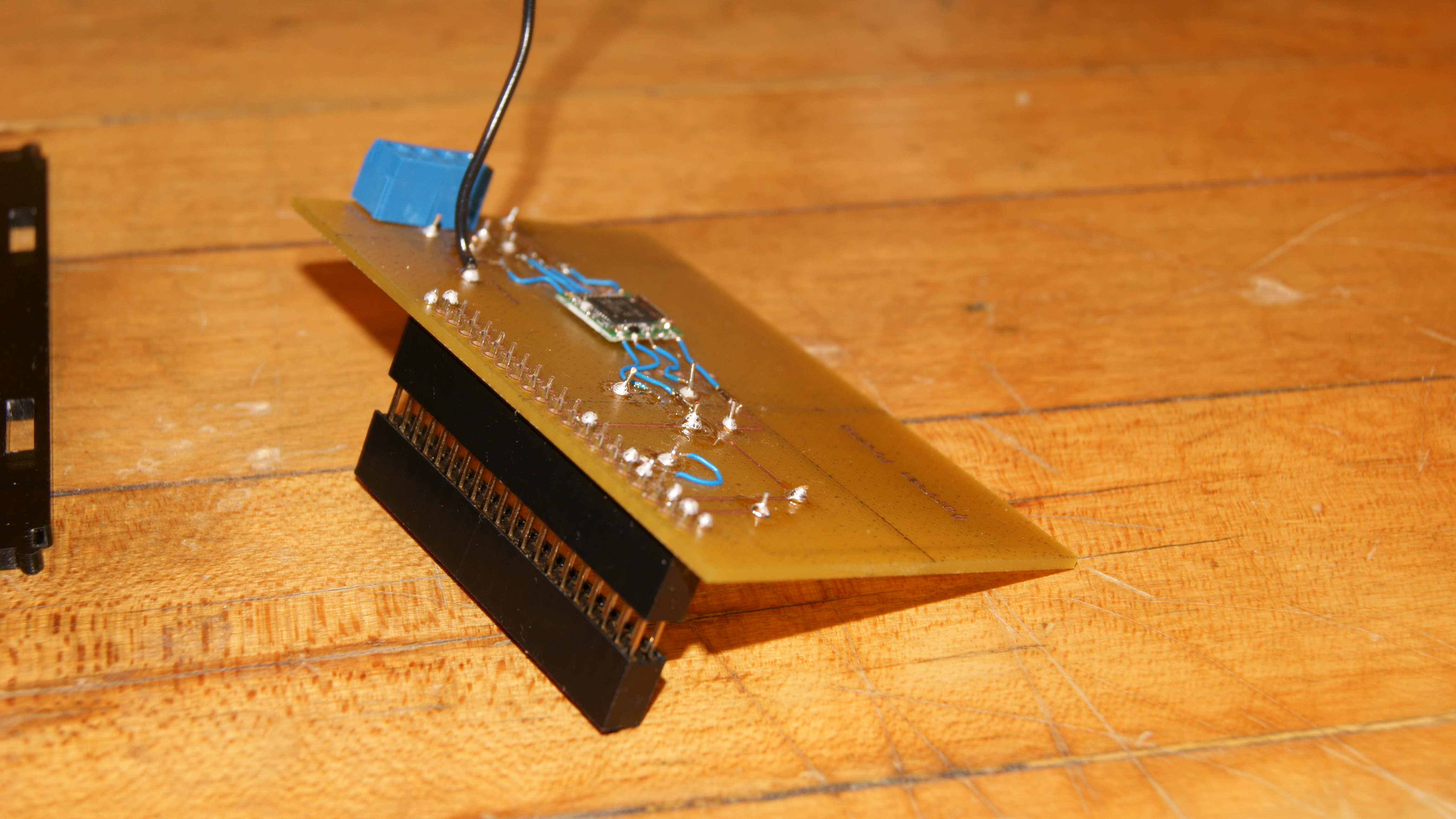
PS. Ignore the jumper wire from the ground trace to pin 5. This was where I made a critical error in my fritzing design. The updated .fzz has fixed this issue.
Next and final step for assembly, attach your PI to the base plate of the acryllic enclosure with the ordered hardware and printed standoffs.
Do one hole at a time. Keep the device firmly planted on a flat surface. (hang over on hole on the edge of a table for example) place the standoffs in between the board and the base plate. Line up the holes, and insert a screw. While keeping the screw in place with your small philips head screw driver, place a nut on the threads with the needle nose pliers. The pliers are to be help still, just keep the nut from turning. Use the screwdriver to tighten, just until enough threads are engaged to hold the screw in place. Repeat for all four holes. Final step is to tighten down snugly, not firmly, on all four screws.
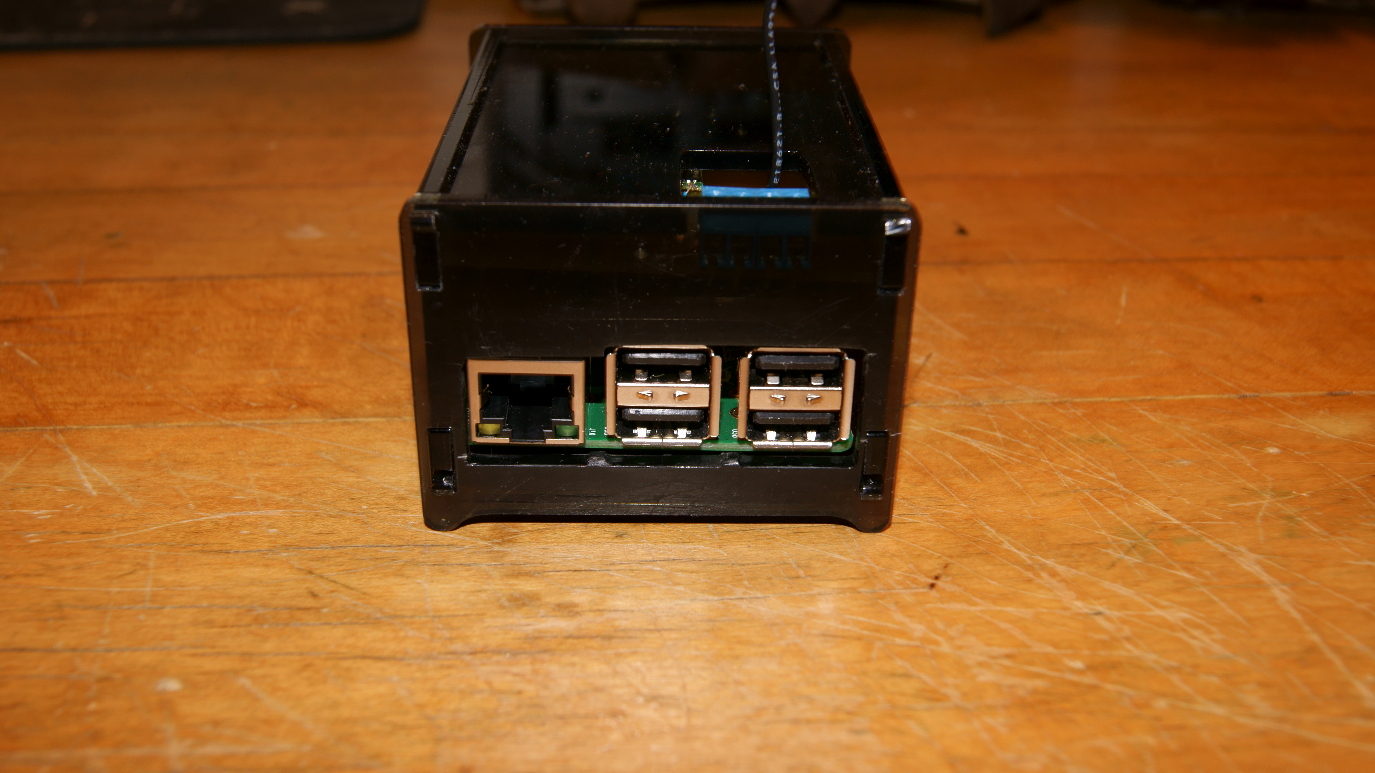
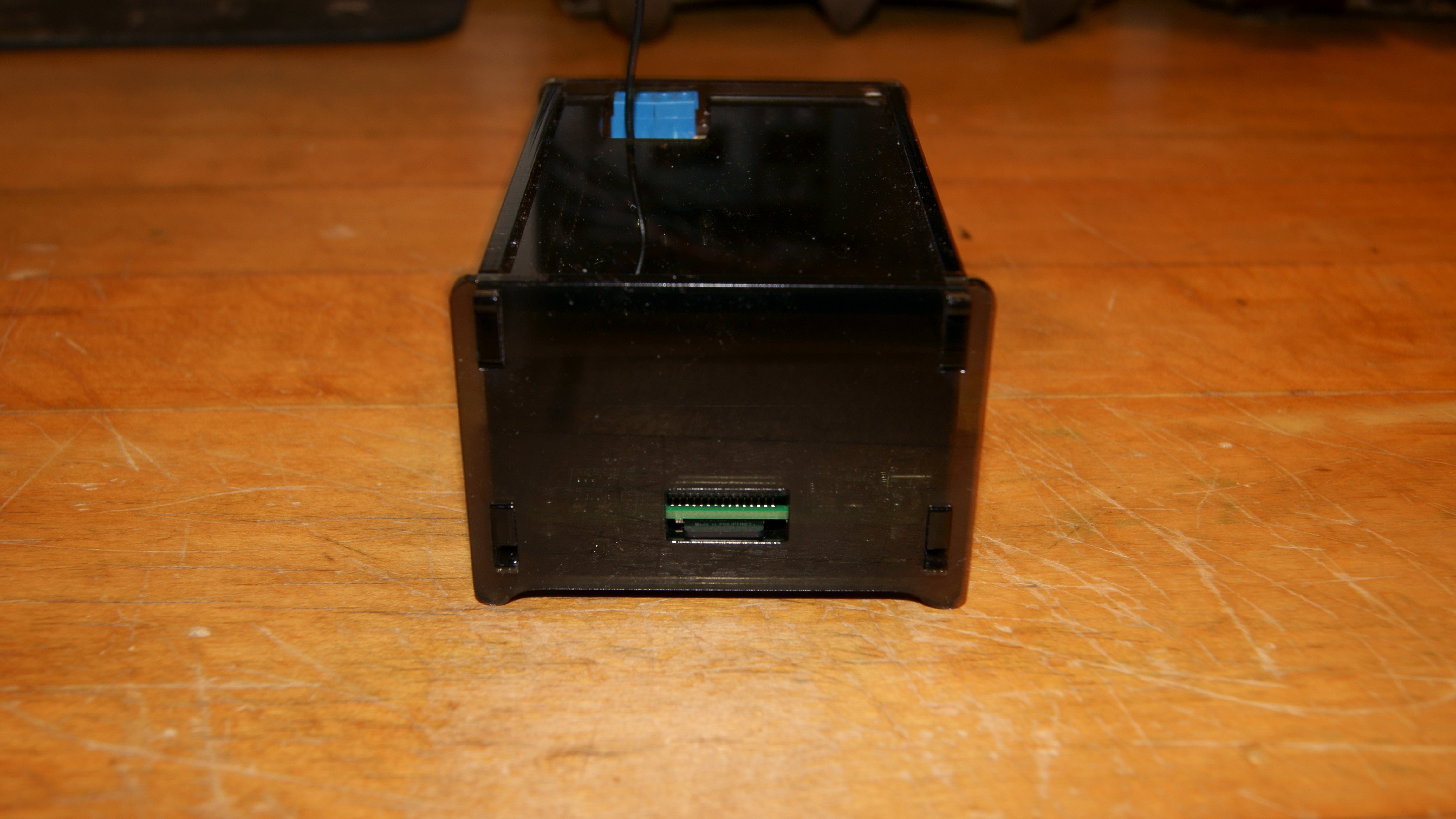
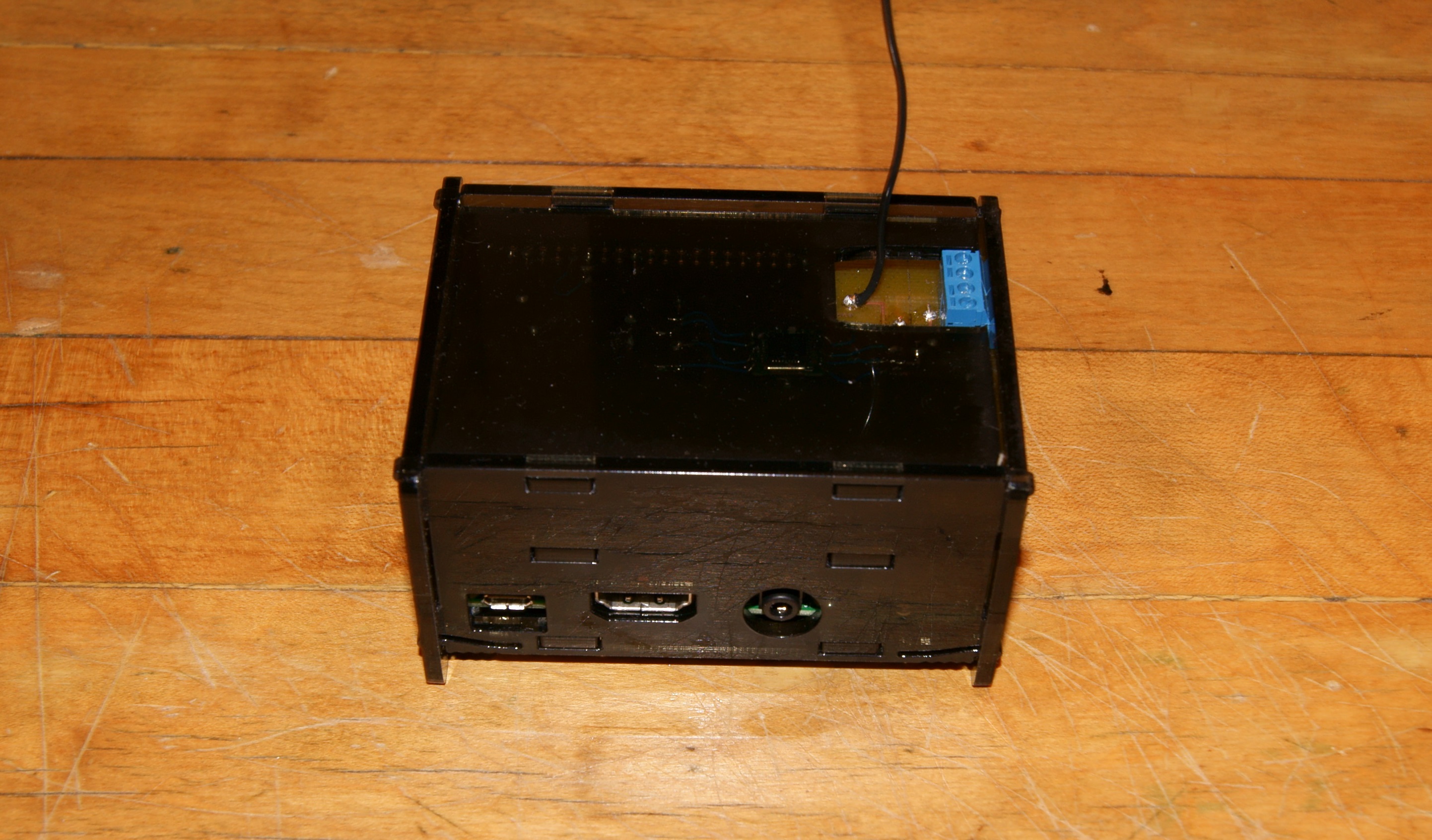
You can now attach all parts of the enclosure to the base, and plug in the PCB/device combo into the GPIO pins.
The final product:
The first step in making sure your PI will be able to play music will be its ability to first boot up, then to enable I2C devices, then to detect that the PI can recognize the sensor.
First, enable the I2C bus on your PI.
Go to: /boot/config.txt
add these lines to the bottom of the file:
dtparam=i2c_arm=on
dtparam=spi=on
dtparam=i2s=on
dtparam=i2c1=on
Next, type:
gpio -v
Make sure you have WiringPi libraries installed If no version is available, please try the following commands:
sudo apt-get install upgrade
sudo apt-get install update
sudo apt-get install i2c-tools
sudo apt-get install wiringpi
sudo apt-get install smbus
Now we need to edit the file
sudo nano /etc/modules
Add these lines here:
i2c-bcm2708
and here:
i2c-dev
at the bottom of the file, and remember to write to file before exiting.
Also, we need to enable i2c at boot. So now we run the:
sudo raspi-config
Next, navigate through the first menu
found this at raspberrypi.stackexchange.com//questions/63076/advanced-options-i2c-not-showing. This shows step by step what to do in a 12 second .gif.
After the I2C bus has been enabled, the /modules file edited and saved, any missing libraries installed; open a new file for editing in VIM. Name the file radio.c.
radio.c

#include <wiringPi.h>

#include <wiringPiI2C.h>

#include <stdio.h>

#include <stdlib.h>

int main( int argc, char *argv[]) {

  printf ("RPi - tea5767 Philips FM Tuner v0.3 \n") ;

  unsigned char radio[5] = {0};

  int fd;

  int dID = 0x60; // i2c Channel the device is on

  unsigned char frequencyH = 0;

  unsigned char frequencyL = 0;

  unsigned int frequencyB;

  double frequency = strtod(argv[1],NULL);

  frequencyB=4*(frequency*1000000+225000)/32768; //calculating PLL word

  frequencyH=frequencyB>>8;

  frequencyL=frequencyB&0XFF;

  printf ("Frequency = "); printf("%f",frequency);

  printf("\n"); // data to be sent

  radio[0]=frequencyH; //FREQUENCY H

  radio[1]=frequencyL; //FREQUENCY L

  radio[2]=0xB0; //3 byte (0xB0): high side LO injection is on,.

  radio[3]=0x10; //4 byte (0x10) : Xtal is 32.768 kHz

  radio[4]=0x00; //5 byte0x00)


 if((fd=wiringPiI2CSetup(dID))<0){

 printf("error opening i2c channel\n\r");

 }

write (fd, (unsigned int)radio, 5) ;

return 0;

}
Once saved as radio.c,
gcc -o radio radio.c -lwiringPi
Credit for the above code goes to "halfluck" on the Raspberry Pi forums.
https://www.raspberrypi.org/forums/viewtopic.php?t=53680&p=419429
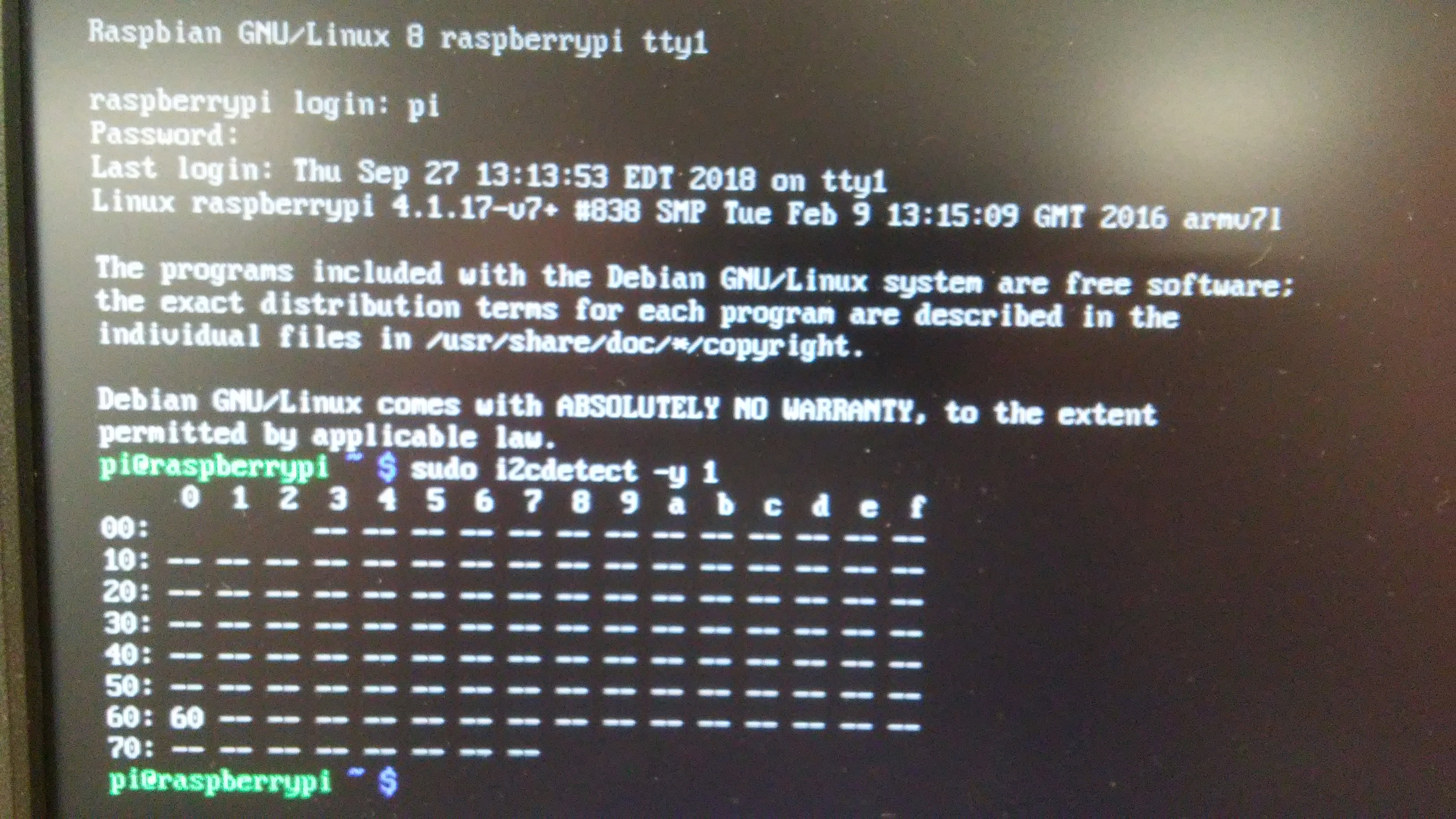
The command to be run here is:
sudo i2cdetect -y 1
This will display all open addresses and will display a hexadecimal value representing the module. We need 0x60.
If you see any other address, there may be some other issue regarding your device; I would look into this guide:
or many others like it across the web.
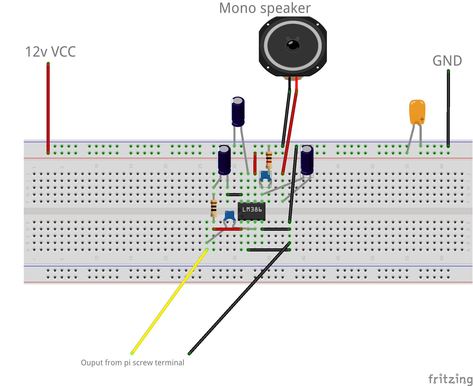
If everything is looking good, you can continue. Now we're ready to play music but most likely you haven't plugged in your speakers. I had two 4.3ohm desktop speakers from an old set I found at my house. One was broken and couldn't play anything, and the other was working just fine. Test them first in your amplifier. Supply a low power frequency to the input of the LM386, shown here:
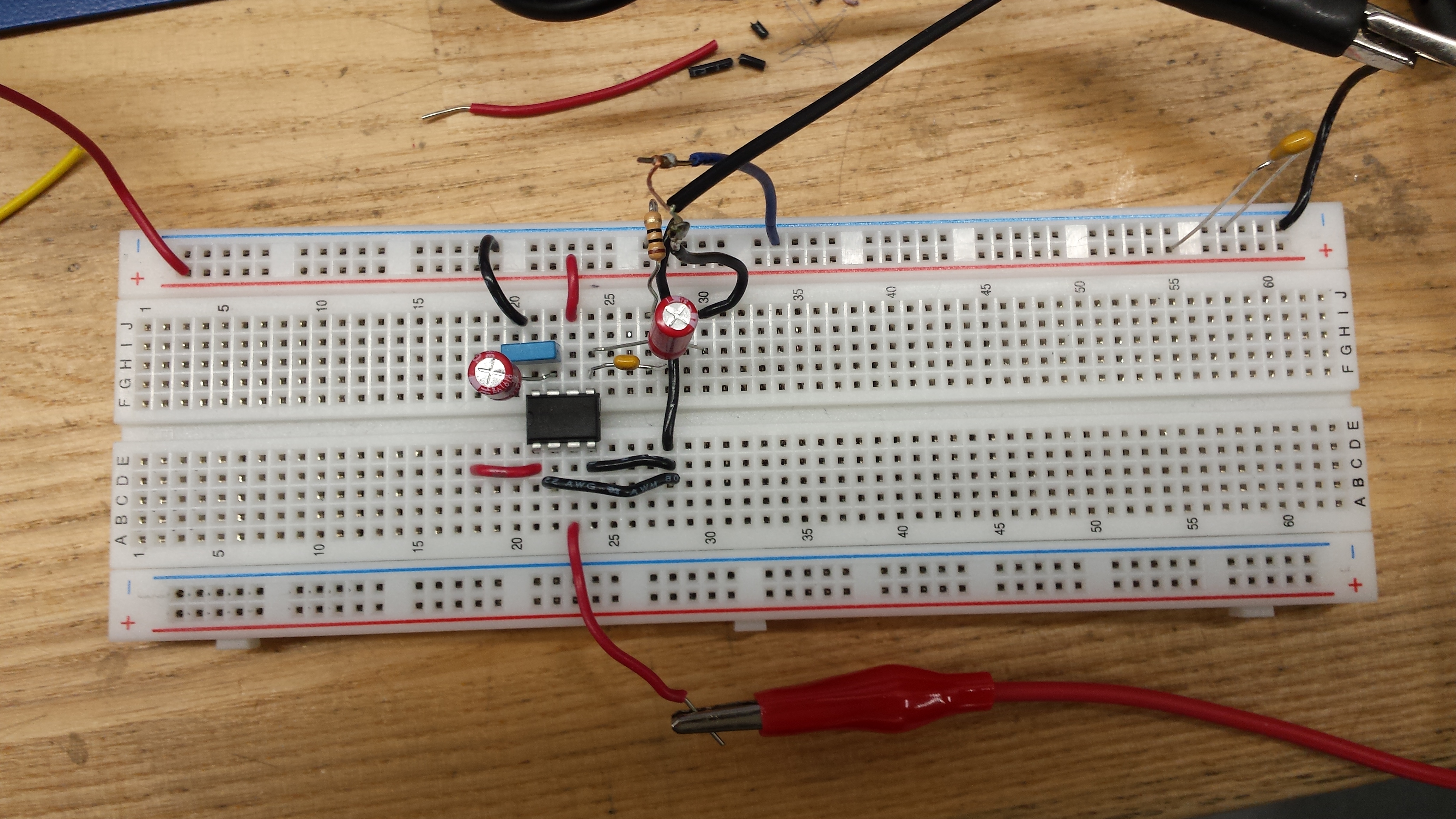
Heres it breadboarded virtually using fritzing:
Once you test has gone through with your speaker, test it out while running the PI hooked up to the amp.
sudo ./radio xx.x //your radio station frequency of choice
It should come out sounding a little something like this: