In this lab, you will implement a binary-to-decimal converter using the double-dabble algorithm and integrate it with your Lab 7 TDM display to show decimal values on the Basys3 board.
The Basys3 switches provide a binary input. Your converter transforms this binary value into BCD (Binary Coded Decimal) digits, which are then displayed as decimal numbers on the 4-digit 7-segment display.
What you will do:
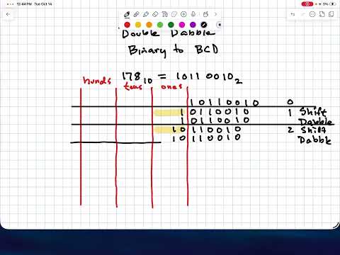
- Study the provided 8-bit double-dabble module and run its self-checking testbench
- Implement a 14-bit double-dabble converter (4 BCD digits: thousands, hundreds, tens, ones)
- Write a self-checking testbench that verifies all values from 0 to 9999
- Integrate your converter with the TDM display and demo on Basys3
Design Hierarchy:
bin_to_dec_top (top-level wrapper)
├── double_dabble_14bit  - Binary-to-BCD converter (YOU IMPLEMENT)
└── hex_tdm              - TDM 7-seg display (provided, from Lab 7)
    ├── counter          - Clock divider
    ├── tdm_scan         - 2-bit scan index
    ├── anode_decode     - Active-low anode selection
    ├── digit_mux        - Nibble selector from disp bus
    └── hex_to_7seg      - Hex-to-segment decoder
- Read the background notes in
background.mdfor the double-dabble algorithm explanation - Study
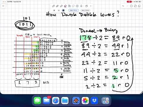
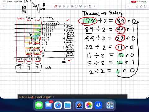
rtl/double_dabble_8bit.v-- this is a complete, working 8-bit implementation - Run the 8-bit self-checking testbench to see it pass
- Work through the algorithm by hand for a small example (e.g., 4-bit binary 9)
- Implement
rtl/double_dabble_14bit.v-- Extend the double-dabble algorithm to 14-bit input with 4 BCD output digits (thousands, hundreds, tens, ones) - Write
tb/double_dabble_14bit_selfcheck_tb.v-- Create a self-checking testbench that tests all values from 0 to 9999 - Complete
rtl/bin_to_dec_top.v-- Wire the converter to the TDM display (TODOs #1-#3)
- Clone or download the Lab 8 template files
- Launch Vivado and create a new project
- Set the project location outside of the template directory
- Add all
.vfiles fromrtl/as design sources - Add testbench files from
tb/as simulation sources - Add the constraint file from
constraints/ - Select the Basys3 board as target
- Read through
rtl/double_dabble_8bit.vand the teaching notes at the bottom - Set
double_dabble_8bit_selfcheck_tbas the simulation top module and run simulation - Verify it reports "ALL TESTS PASS"
- Trace through the algorithm by hand for input = 42 (8'b00101010)
- Open
rtl/double_dabble_14bit.vand implement the algorithm - Key differences from 8-bit: 14-bit input, 4 BCD digits, 30-bit stage width, 14 iterations
- Follow the pattern from
double_dabble_8bit.vbut with wider stages - Refer to
background.mdfor the bit indexing layout
- Open
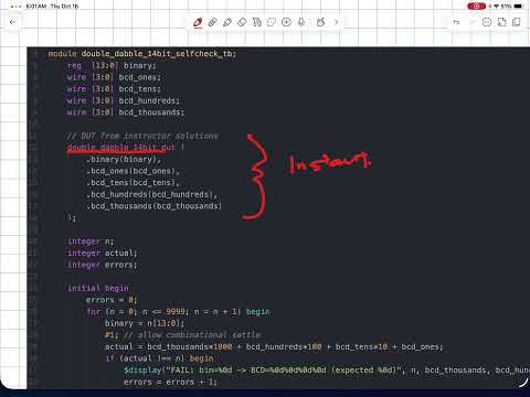
tb/double_dabble_14bit_selfcheck_tb.vand implement the testbench - Model it after
tb/double_dabble_8bit_selfcheck_tb.v - Test all values from 0 to 9999 (exhaustive for the displayable range)
- Reconstruct decimal from BCD:
thousands*1000 + hundreds*100 + tens*10 + ones - Compare to original input; report FAIL for any mismatch
- Print a final PASS/FAIL summary
- Open
rtl/bin_to_dec_top.vand complete TODOs #1-#3 - TODO #1: Declare BCD wires
- TODO #2: Instantiate
double_dabble_14bitto convertsw[13:0]to BCD - TODO #3: Pack BCD digits into
disp[15:0]as{thousands, hundreds, tens, ones}
- Set
double_dabble_14bit_selfcheck_tbas the simulation top module - Run behavioral simulation and verify "ALL TESTS PASS"
- Fix any failures before proceeding to hardware
- Set
bin_to_dec_topas the top module for synthesis - Synthesize, implement, and generate bitstream
- Program the Basys3
- Verify: set switches to binary 42 (sw[5]=1, sw[3]=1, sw[1]=1) and confirm display shows "0042"
- Test additional values: 0, 100, 255, 999, 1023, 5000, 9999
When you push your code, GitHub Actions will automatically compile and test your modules:
| CI Job | What It Tests | Files Compiled |
|---|---|---|
test-double-dabble-8bit |
8-bit converter (provided, should always pass) | double_dabble_8bit.v + double_dabble_8bit_selfcheck_tb.v |
test-double-dabble-14bit |
14-bit converter + your testbench | double_dabble_14bit.v + double_dabble_14bit_selfcheck_tb.v |
Both jobs must show PASS for full credit.
├── rtl/
│   ├── double_dabble_8bit.v     # 8-bit converter (provided, study this)
│   ├── double_dabble_14bit.v    # 14-bit converter (YOU IMPLEMENT)
│   ├── bin_to_dec_top.v         # Top-level integration (YOU COMPLETE)
│   ├── hex_tdm.v               # TDM display wrapper (provided)
│   ├── counter.v               # Clock divider (provided)
│   ├── tdm_scan.v              # Scan controller (provided)
│   ├── anode_decode.v           # Anode decoder (provided)
│   ├── digit_mux.v             # Nibble mux (provided)
│   └── hex_to_7seg.v           # 7-seg decoder (provided)
├── tb/
│   ├── double_dabble_8bit_selfcheck_tb.v   # 8-bit testbench (provided)
│   └── double_dabble_14bit_selfcheck_tb.v  # 14-bit testbench (YOU WRITE)
├── constraints/
│   └── basys3.xdc              # Pin assignments for Basys3
└── .github/workflows/
    └── test.yml                 # CI - auto-tests on push
| Port | Pins | Description |
|---|---|---|
clk |
W5 | 100 MHz system clock |
btnC |
U18 | Center button = synchronous reset (active-high) |
sw[15:0] |
V17..R2 | 16 slide switches (binary input; sw[13:0] used for conversion) |
| Port | Pins | Description |
|---|---|---|
seg[6:0] |
W7..U7 | 7-segment cathodes {g,f,e,d,c,b,a} (active-low) |
an[3:0] |
U2..W4 | 7-segment anodes (active-low, one-hot) |
| BCD Digit | Display Position | Anode |
|---|---|---|
| ones | Rightmost (digit 0) | an[0] |
| tens | Second from right (digit 1) | an[1] |
| hundreds | Third from right (digit 2) | an[2] |
| thousands | Leftmost (digit 3) | an[3] |
The largest decimal value that can be fully shown on 4 digits is 9999 (binary 14'b10011100001111 = hex 16'h270F). Inputs above 9999 convert correctly to BCD but require a 5th digit that the Basys3 cannot display.
Demo your working hardware to the instructor during lab. Set different switch patterns and show correct decimal values on the Basys3 display.
No code submission is required -- GitHub CI will verify your Verilog automatically when you push.
- Wrong decimal output: Check add-3 logic (must be
>= 5, not> 5); verify you add 3 before shifting - Off-by-one: Ensure you have exactly 14 iterations for 14-bit input
- Incorrect bit indexing: BCD digits are in upper bits:
[29:26]thousands,[25:22]hundreds,[21:18]tens,[17:14]ones
- Testbench never finishes: Make sure your loop runs 0 to 9999, not 0 to 16383
- All tests fail: Check that BCD outputs are connected in the right order
- Display shows hex instead of decimal: Verify
bin_to_dec_topconnects BCD digits todisp, not raw switches - Display flickers: The provided TDM modules use N=20 for the clock divider; adjust if needed
- Wrong digits displayed: Verify BCD packing order:
disp = {thousands, hundreds, tens, ones} - Some digits always zero: Check that
sw[13:0]is connected to the converter input