Troubleshooting EM2
-
Viewing raw sensor output
- Data writing to OS drive. (EM1)
- Blank monitor or unclear picture.
- Camera screen blue/frozen (EM1)
- PSI user interface red or saying no/low connection.
- PSI "OverVoltage" Problem
- Faulty Internal Amp
- GPS user interface red, saying "NO DATA".
- GPS user interface is red, saying "NO GPS FIX"
- RFID Scanner not scanning
- RFID scanner not counting
- RFID scans show on screen but no noise.
- "Using OS Disk" error message
- Camera Output Is Blank (V2XX)
- Missing Video Archives
Table of contents generated with markdown-toc
Table of contents generated with markdown-toc

- Unplug all sensors from the box. Ensure power cable, VGA cable and keyboard cable are correctly plugged into their correct ports. Try to turn box on.
- Unplug power cable from box and ensure power cable is connected to boat's 12V DC power supply. Measure power supply voltage to ensure ~12DC is being provided.
- Open up box and ensure box's internal battery is connected to box's PSU correctly.
- Measure battery terminals to ensure 12V is being provided by battery.
- If, while unplugged from the boat's 12VDC power supply, the box powers up under battery power, check the pins, cables and connections of the red and black wires connected from the box's "Power" port to the upper two terminals on the PSU's "power in" side. Ensure they are all seated correctly and connected to the proper pins/terminals. The top most terminal on the PSU's "power in" side is positive and the second from the top is ground.
- Measure voltage across PSU's positive out terminal and any ground, ensuring 12V is leaving PSU. Be careful not to accidentally short out box. If voltage = 0 then check the PSU's fuse and replace as needed.
- Check connection of box's main power button. Ensure it's two wires connect to the two correct pins on the motherboard (its two pins should have red bases). Using a multi-meter test continuity by unplugging the wires from their pins and depressing the power button.
- Unplug motherboard's power cable and measure voltage across it. If its not getting 12V DC then ensure its connection to PSU is good.
- Ensure yellow wire from Power Relay to Pin Housing connected to box's main power button is connected correctly to pin#9 (lone pin).
- Check continuity of any screw on motherboard to all 4 of the big bolts on bottom of box (not the ones attached to the feet). If continuity = 0 then visually inspect under motherboard to see if any of those bolts are touching and shorting out the motherboard. If they are, back off bolts until they are not touching and try powering on the box again. If box successfully powers on after this it is advised that control box be replaced as the motherboard may be permanently faulty.
- Replace control box.
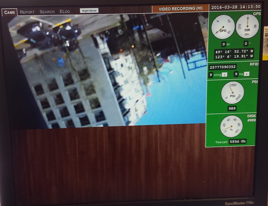
The screenshot above shows a fully functional system. Notice all sensor boxes are green and double check all the information such as time/date and GPS location are correct and PSI and HD disk space are at an expected value.
Depending on the sensor
##Local Networking To set up local networking with other computers outside the camera network, you need to copy the following file to the /var/ directory, so you have a file like "/var/network" if you want to ssh into the box.
https://github.com/Ecotrust-Canada/em-control-box/blob/maint/templates/network.template
One EM2 and up, use the screen command.
For the GPS
screen /dev/ttyS0
For the RFID
screen /dev/ttyS1
For the Arduino
screen /dev/ttyUSB0
Ensure VGA cable is fixed securely at back of control box and screen. If no change there is also a short VGA cable internally within the control box which should be checked. Test if it is the monitor at fault by either connecting a different monitor to the control box, or trying a different connection into the monitor.
Ensure the connection into the control box is good and the wires are correctly inserted into the connector plug. If possible test the voltage being produced by the sensor into the box using a multi-meter. Testing between the sensor cable to a ground should produce a reading of around 1v (between 0.8 -5v) if working correctly. Check over wire to see if any joins or kinks may have broken the connection.
(EM1) - In the terminal, typing sudo putty will bring up a Putty window. Select serial, and ttyUSB0 and hit okay. Here you will see P### -newline- B### -newline- and so on. the number following P represents the voltage to pin A0 on the Arduino. The number compared to 1023 will be equal to the ratio of the voltage received to the Arduino voltage. For example, if the Arduino is the 5 volt version, an idle reading of P100 is healthy for a 5VD configuration, because a healthy sensor will produce ~ 1 volt, which is then divided in two (.5V) inside the box by the voltage divider. The 5V Arduino will then read the .5V --> (.5 / 5) x 1023 ~ 100. If you are getting a low reading here but it is consistent, you can try lowering psi_vmin in the config file, but take note this may indicate a sensor change impending; the sensor seems to output lower voltage near the end of its life.
If the output format for /dev/ttyUSB0 is not: P### B### .... but instead:
P###:B###:P###:B###...
The Arduino is flashed with the code for EM2. If you're on an EM1 box, you'll need to have spare Arduinos with the correct program. If you're on an EM2 box and have the first format (newlines) you can access the Arduino code through /opt/em/arduino/rec-adc.pde, adjust the printing commands slightly, and flash the arduino with em flashard
Note that when wire to A0 is taken off sometimes value read from A1 "leaks" on to A0 (pin has floating voltage).
Note that in using this method one needs to know the config i.e: 3V, 3VD, ... etc
A low putty reading (or equivalently, voltmeter reading inside the box) with a known good sensor attached indicates wiring problems. if you have a sensor attached to an end that you can quickly pop on you should see this putty reading go back up to a healthy value. If not, this indicates a problem between the box terminals and the Arduino itself.
If a known good sensor produces a good signal but the current one is producing a low/unreliable signal you need to either change the line or the pressure sensor or both. The current strategy has been to make the box end on a long wire, and while the sensor end of the cable is still skinny and unattached to anything, wire it through the cabin as you would on an install. Cut the existing sensor cable (POWER OFF) and try the old sensor with the new cable; if it indeed was the sensor, the price of the cable is negligible compared to the cord, and it will be good to have a new cord anyways. You can solder or twist the wires together, noting whether the previous technician has used the convention that black is ground, or the uninsulated "plain" is ground, and see if that betters your connection. Still nothing? --> New sensor. In this case replace the sensor but make sure to put all of the shrink wraps you will ever use in this job on the unsoldered wires first.
By the way, you can check if 2/3 of the cable to the sensor is good after you've cut. if you go back and turn the power on to the sensor, you can measure near the sensor if the cable was at least delivering power.
(EM2) - Some differences are that instead of putty we can access this data through cat < /dev/ttyUSB0.
Also, pins should not float at weird voltages in EM2 when not hooked up as we set pins A0, A1, A2 to LOW.
Sometimes a box may contain a 3.3V arduino that has the pressure sensor wired directly into one of its analog pins. This is characterized by the voltage reading reaching a certain threshold and then dropping down to 0 (presumably as voltage exceeds the pin's limit. Then, as the voltage comes down into the acceptable range the voltage reading will jump back up to a legitimate/high value and then track back down with the falling pressure. This results in double peaks. You may need to add a voltage divider or replace the arduino with a 5V version. Important: you must use a corresponding 5V FTDI chip as well, or the problem won't go away.
A weak or distorted amp sound may be the result of a blown transistor in the horn amp (for boxes with internal amps). Check to see that with no input the voltage across the third stage (PN2222's) is 12V. If there is significantly less than this then one or more of those transistors is blown. This will usually be accompanied with a red-hot transistor. If both blow, you will begin to hear distorted amp sounds as the x-istors heat up. Replace the blown transistors and make sure the input line is clean of any errant signals.
- Check the wires are correctly inserted into the connector plug.
- Ensure the connection to the GPS (cable) is full secured at both ends. It may have come loose on the GPS end if the locking sleeve wasn't fully engaged.
- Try connecting a different GPS if possible to test before re-wiring or replacing the unit.
- Record the message in the red GPS sensor area on the screen. ie, does it say "NO GPS FIX" or "NO DATA" ?
- Ensure the connection to the GPS (cable) is fully secured at both ends. It may have come loose on the GPS end if the locking sleeve wasn't fully engaged.
- Restart the system.
- If none of these succeed, remove the gps mounting bracket, and put the GPS in plain view of the sky via a window for testing. Does this fix it? If so, or if it was just periodically cutting out at sea, it needs a new mounting location with no steel or other dense material blocking the line to the sky. This may be a downside of mounting the GPS units inside the wheelhouse and on some vessels we may find the need to move the aerial.
Test with more than one chip to ensure the problem is with the scanner. Ensure the connection into the control box is good and the wires are correctly inserted into the connector plug. Check over wire to see if any joins or kinks may have broken the connection. If the scanner has been used for many years ensure it has not worn to the aerial or chip. Check to see how scanner was mounted. RFID scanners should be mounted to a wooden block which in turn is mounted to the deck rail of the boat. If a scanner is mounted with metal bolts directly to a metal deck rail, signal interference may occur causing the RFID scanner to not perform properly. To test this, un-mount scanner and try scanning a known good RFID chip. If the scanner works, re-mount the scanner properly.
Sometimes the scanner looks as if it's not scanning but the scans are being registered in the system, and just not showing on the display. If the scanner is a translucent scanner, scan a few chips and look inside it for its green LED to blink. Either way, look inside /mnt/data/RFID_DATA.CSV and try to find your recent scans. If in fact they are there but not counting on the user display, know that this problem has been solved more than once by re-imaging the system. You can also open Putty (EM1 Only) with sudo putty, selecting ttys1 and scanning to see your scan pop up in that terminal as some characters.
Ensure the horn is plugged in and its cabling is undamaged. Ensure the amp is wired correctly inside the control box. Ensure the amp has power, on most amps a red light should be visible. Adjust the volume control and other settings to max. Test the connections from the amp to the control box are plugged securely. Ensure the speaker wire is connected and shows no sign of corrosion. View the horn to make sure it is not damaged.
(EM 1) - Try to make the horn sound by going into Putty (See PSI section above) and again selecting serial device ttyUSB0. Type (it won't show) F500D1000E. 500 here could be anything from 500-6000 (frequency) and D can be 500-10000 (milliseconds). E means execute the horn sound with these parameters. If you don't hear the sound, or see some weird format in Putty (see PSI section above for format), you might suspect an Arduino problem, and throwing in a new one of these is a fast check (It must be a programmed one for EM1). Another quick check is taking a new horn, and hooking it up to the amp directly. Try the instruction again. If it worked this time, you know it is either just the horn, the horn cable, or both. If, however, the horn sounded not through the amp, you can try to carefully put the horn wires into the horn port on the box. Again try to sound it in putty. If you get a sound here, but not directly from the amp, you can suspect the amp as a source of the problem. When you try a new amp, actually just try hooking it up to the existing horn and box. The amp is the last piece to suspect but if it is the only piece with a problem this may be the fastest way to fix the horn problem.
An extra note on horns - When a horn problem exists solely in conjunction with a psi problem, the Arduino should be the first thing to come into suspect.
If the OS drive is full, that means the system's been running with no data drive.
When possible, it's best to avoid letting it get like that, because in some cases it might be hard to recover. Whenever the system reads "using OS disk" (or is red for any reason) it needs to be fixed because it can lead to further problems.
Before cleaning up the OS drive, install a data drive and ensure it's recording there.
The system has two data recording locations, /var/em/data is the version on the OS drive, and /mnt/data is the DATA drive.
If you don't care about the data, you can delete data in the folder /var/em/data/ ie)
rm -rf /var/em/data/*
Be careful to enter the above command exactly, as deviations of it could cause issues. If you need to keep the data from the OS disk, just move everything to the data drive. ie)
rsync -av /var/em/data/ /mnt/data
Camera video does not show up in UI.
- hit ctrl-alt-backspace to reset the UI.
- ensure the camera, switch and computer are powered on and connected. Their network ports should all be blinking wherever plugged in.
- ensure camera's connected. In the command line type:
ping 1.1.1.1
If it says the camera is "Unreachable", there's a networking issue (ie, not physically connected, bad cable, not powered on, etc.)
To reset the EM service: systemctl restart em-rec.service
If there are intermittent cases of one or more cameras missing in your online video which has freshly been uploaded, Here are steps to investigate, in order:
-
Was the data interrupted while uploading, or didn't finish? Check the boat drive if you still have it. To catch this, we'd need to check as soon as the data's initially checked.
-
On the vessel, ensure 4 video files (one for each camera) is recording on the box when you're there.
-
One cause if #2 is negative is that you have a duplicate camera IP address. It could happen if a camera was replaced recently for instance.
If there's still an issue after these steps, let's work on this on our weekly tech call.