GL Communications Manual
[TOC]
The communication protocol of the GL controller system is a general-purpose communication tool that allows communication between the conventional equipment, such as a computer and the GL controller via a communication interface. This interface makes it possible to control the chamber, including monitoring operation status, controlling operation or executing program with commands sent from the computer. The GL controller system can be configured to support different communication types, as described in the following sections.
TCP/IP (Transmission Control Protocol/Internet Protocol) is the standard, foundational protocol suite that governs how data is packaged, addressed, and transmitted, ensuring reliable communication between network devices. The GL controller Ethernet interface is based on TCP/IP. The communication port for the TCP socket assigned for the GL controller is 10001.
The GL controller supports DHCP (Dynamic Host Control Protocol) or static network configurations. By default, the GL controller applies DHCP to join the network, using an IP address assigned by the DHCP server. If DHCP service is not available, it uses a preconfigured Class C network protocol to set its IP address (called fallback IP) as follows:
IP Address: 192.168.0.83; Subnet Mask: 255.255.255.0; Gateway: 192.168.0.1
This protocol occurs when GL is connected directly to a computer or a network hub without the DHCP service.
A static IP address for the GL controller can also be configured and used on a DHCP network. Section 2.1.4 provides more details on IP address information on these types of network.
RS-232C (Recommended Standard-232) is a serial interface widely adopted for transmission between computers and peripheral devices based on a communication standard of the EIA (Electronic Industries Association). The interface connector will differ according to the connected computer. Check the specifications of your computer and prepare a cable that can make the signal connections via the RS-232C interface.
The RS-232C was designed for slow, point-to-point, asynchronous communication. Its interface can be adapted using a USB converter for a computer that does not have an onboard serial port.
RS-485 is a serial interface standard for multipoint communication lines, adopted by the EIA (Electronic Industries Association). While RS-232C requires a one-to-one connection, RS-485 by contrast enables n-to-n connections. However, with the communication system used in this manual, the connection is one-to-n.
The RS-485 interface uses a DB-9 connector with RS-485 cable specified by ESPEC. A USB adapter is available for this type of interface.
GP-IB (General Purpose Interface Bus) is a standard parallel interface used for attaching sensors and programmable instruments to a computer. It is officially known as IEEE-488 (Standard No. 488 of the Institute of Electrical and Electronic Engineers [USA]) and was based on the HP-IB (Hewlett-Packard Interface Bus) standard protocol of Hewlett-Packard Company.
The GP-IB conforms to IEEE-488 which uses a communication cable compatible with IEEE-488 standard protocol.
Note: GP-IB communication is currently not supported on the GL controller system.
Data transmitted with the communication function consists of two types, called Command Data and Response Data. This data can be handled by all four communication interfaces (namely, Ethernet, GP-IB, RS232C and RS485).
Note: The word data being used here refers to a "packet" of information represented by a stream of characters or binary digits (or bits). This single packet is what we called data. Data is not case sensitive; command data can be issued in lower case or upper case ASCII characters.
Data sent from the computer to the GL chamber is treated as a command. Command data is further divided into two types: (1) Monitor Commands and (2) Setting Commands.
| Type | Description |
|---|---|
| Monitor Commands | These commands are used to monitor the chamber operating status or conditions inside the chamber. |
| Setting Commands | These commands are used to change the chamber operating mode or conditions inside the chamber, such as target temperature and humidity. |
Response data returned by the chamber in response to the command data is called a response. This response is divided into two types: (1) Reception status and (2) Monitor data.
| Type | Description |
|---|---|
| Reception Status | This response tells the computer whether the setting command sent was processed correctly or not.
|
| Monitor Data | This data is sent in response to monitor commands from the computer.
|
Command data requires proper structure and syntax for the GL control system to understand and carry out the task. The following table outlines the command data and response data used by the four communication protocol covered in this manual.
| Type | Command | Response |
|---|---|---|
| LAN | [Command Data][delimiter] | [Response Data] [delimiter] |
| RS-485 | [address][Command Data][delimiter] | [Response Data] [delimiter] |
| RS-232C & GP-IB | [Command Data][delimiter] Note: In consideration of compliance with the old transfer protocol, it is possible to recognize even if an address is added to the front of the above command. [address][Command Data][delimiter] |
[Response Data] [delimiter] |
Note: The delimiter is fixed with CRLF for all types of communication.
Command data may consist of the main command(s) and optional parameter(s). They both are expressible in upper-case or lower-case ASCII text. Spaces between characters are automatically deleted or ignored; they are generally used for readability.
The GL controller can handle three types of numeric data: integer, real and integer/real switchable data.
| Data Type | Description |
|---|---|
| Integer | Integer data include numbers of cycle, program number, time, etc. |
| Real | Real data involve heater output value, valid to the first decimal place (round off to the second decimal place and discard any decimals thereafter.) |
| Integer/Real | Such data type apply to temperature settings and temperature measurements. The value is rounded off to the first decimal place; any digits after the first decimal place are discarded. |
For data that can be switched between integer and real numbers, switching is possible in manufacturer maintenance mode, as described in the following table. It depicts four switchable setting mode offered by manufacturer maintenance, processing for setting commands and monitor commands.
| Mode | Setting Command | Monitor Command |
|---|---|---|
| 0 | Treat as an integer | Integer notation |
| 1 | Treat as an integer | Real number notation |
| 2 | Treat as real number | Integer notation |
| 3 | Treat as real number | Real number notation |
Example: (Integer Notation)
The number is expressed by rounding off to the nearest whole number. Here is an example of integer notation used in a response to the monitor command:
cmd> TEMP?
rsp> 23,50,200,0
Example: (Real Number Notation)
The number expressed by rounding off to the second decimal place. Here is an example of real notation used in a response to the monitor command:
cmd> TEMP?
rsp> 23.5,50.0,200.0,0.0
Example: (Integer Notation)
The number expressed by rounding down to the one decimal place. Here is an example of integer notation used in a response to the setting command:
cmd> TEMP,S23
rsp> OK. Setting (set point is recognized as 23°C)
cmd> TEMP,S23.6
rsp> OK. Setting (set point is recognized as 23°C)
Example: (Real Number Notation)
The number expressed by rounding down to the second decimal place. Here is an example of real number notation used in a response to the monitor command:
cmd> TEMP,S23
rsp> OK. Setting (set point is recognized as 23°C)
cmd> TEMP,S23.6
rsp> OK. Setting (set point is recognized as 23.6°C)
cmd> TEMP,S23.69
rsp> OK. Setting (set point is recognized as 23.6°C)
When command data sent from the computer has syntax errors (i.e., incorrect format or typo) and is not correctly processed by the GL controller, the chamber returns an “NA :” code attached with an error message as explained in the following table.
| Error Message | Error Description | Example |
|---|---|---|
| CMD_ERR | Main command error | "ROM?" entered as "RUM?" |
| ADDR ERR | Incorrect address | Incorrect use of proper address |
| PARA ERR | Option parameter error | Missing a required parameter or text entered for numerical-only parameter |
| DATA NOT READY | Specified data does not exist. | An unregistered program number was specified. |
| DATA OUT OF RANGE | Specified value outside the setting range | Specify "TEMP,S300" for the setting range of 0°C to 200°C. |
| PROTECT ON | Setting prohibited by network [Set Protection] - [Remote setting] is set to [ON] on the chamber. | Attempt to change the temperature set point while the remote setting is on |
| INVALID REQ | Unsupported function specified | A command related to the time signal was sent to a chamber not equipped with the time signal option. |
| CHB NOT READY | Command specified when the chamber is not ready to receive (see Table 3.11 for details) | Attempt to change KEYPROTECT when the panel power is off "PRGM,PAUSE" (pause) was executed when the chamber was stopped. |
Understanding the difference between "program operation" and "remote operation" is crucial. When changing the chamber from constant operation (the function for operating with the same settings) to an operation that changes automatically with the elapsed time, there exists two different methods referred to as program operation and remote operation. They are described in detail in the following sections. Familiarize yourself with the differences between the two and use them accordingly.
| CAUTION | When working in or near the test area, do not use LAN or remote network operations. Sudden operation of the chamber can result in injury to those working in or near the area. If remote operation is possible, implement protective measures, such as enabling remote operation protection. For details about configuring the protection settings, refer to GL Controller Operation Manual, Section 6.5 for details. |
Program operation refers to an operation that uses program data that can be edited and executed on the instrumentation. The following table lists the advantages and disadvantages associated with this type.
| Type | Description |
|---|---|
| Advantage | Operations are managed on the chamber until the program ends and are not affected by computer operations (including network connection issues and computer shutdown). |
| Disadvantage | No restrictions on the number of programs but storage space on the GL controller system may affect how many programs can be stored. |
Remote operation refers to a single-step program operation that can be issued and executed from a computer remotely on the network. The following table lists the advantages and disadvantages associated with this type.
| Type | Description |
|---|---|
| Advantage | Operates on a remote computer; it does so without restrictions of the chamber (such as number of steps and programs); program instructions can be created. |
| Disadvantage | Affected by computer operations (including network connection issues and computer shutdown); careful consideration must therefore be given to the possibility of the program shutting down and no longer being executed. The computer that hosts the software must be connected at all time for the operation. Since program is not stored on the system, program step must be reissued for each operation. |
The following procedure outlines the steps to send commands to and receive responses from the GL controller system.
Procedure:
- Send command to address 1.
- Receive response from address 1.
- Wait a fixed period of time depending on the type of command sent in step 1. See the following description regarding the delay time.
- Send command to address 1.
The following diagram outlines the communication path taking place between the GL controller system and the computer that hosts the communication protocol.
The diagram depicts the two sets of arrowed paths (setting commands and monitor commands) taking place between the two devices. The first set occurs when a processable setting command is received and processed successfully. The second set occurs when a processable monitor command is received.

When the protocol is set using the old mode, the echo back mode can be selected. When echo back is enabled, the chamber returns the response data in response to the command data from the host computer with the following format.
| Response Type | Description |
|---|---|
| Setting Response | [reception-state-data] [delimiter ] |
| Monitor Response | [reception-state-data][delimiter][monitor-data][delimiter ] |
Therefore, when the response data to the delimiter is treated as a single data, the data transfer is as follows.

The following diagram depicts communication process when echo back is disabled. When echo back is disabled, the chamber does not return the response data in response to the command data from the host computer until the data transfer trigger is received.
On this network, "address,G" is sent to the chamber instead of the command data, and this is treated as the data transfer trigger.

Both RS-232C and RS-485 communication follow the standard protocol (similar to LAN Ethernet connection with the only difference between TCP/IP and serial). The following diagram depicts the communication process.

The delay time for the monitor command is 0.2 seconds or longer. For a command with large processing load, a delay time can take up to 0.5 seconds.
The delay time for the setting command is 0.5 seconds or longer. For a command with large processing load, a delay time of 1.0 second or more is required after the GL controller received the command.
Note: If there is response data, be sure to receive the response data before sending the next command. Otherwise, normal communication may not be possible. When sending commands to the same address, provide a delay time from the time reception is complete to the time the next command is sent. Otherwise, the network load may prevent normal control.
As previously mentioned, the GL controller system supports four different communication types: RS-485, RS-232, GPIB and LAN. The LAN communication is standard; and, by default, it is available on all GL controller systems. These communication methods are listed in the Set Communication page, as depicted in the following figure.

| No. | Name | Description |
|---|---|---|
| 1 | Path Indicator | Path to Set Communication; it indicates the path to the Set Communication via the Menu bar or the Hamburger menu |
| 2 | Communication Type | Lists of available communication protocols: RS-485, RS-232, GPIB, LAN. The LAN communication is standard, which is available on all GL controller systems. |
| 3 | LAN Communication | Configuration page for LAN communication; it is the standard setting. |
| 4 | Network Status | Displays network status, interface and configuration protocol |
RS-485 (Recommended Standard-485) is a serial interface for multi-point communication lines that was adopted by the Electronic Industries Association (EIA). Note: The RS-485 used here is the standard protocol. Echo back and protocol selection options are not available.
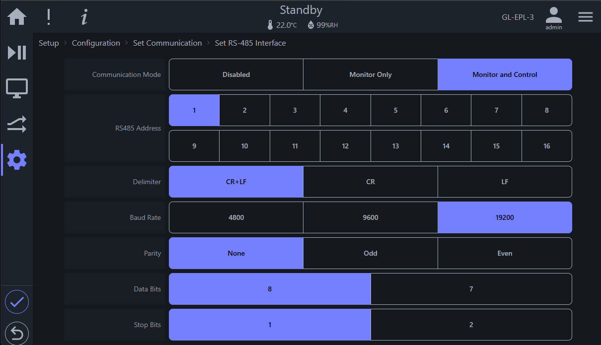
The following figure depicts the RS-485 setup screen. If this communication type is available on your GL controller system, it is enabled via the Service menu (a menu only available to ESPEC service technician or engineer). When attempting to communicate via the RS-485 protocol, make sure that the configuration on the client side has a matching set of parameters as illustrated in the figure (described in the accompanying table). This setting overrides any parameter on the client device.

| No. | Name | Description |
|---|---|---|
| 1 | Address | Specify the address number from 1 to 16. The address number is assigned to identify the chamber. Make sure that it is not the same as the address of other chambers. |
| 2 | Delimiter | End packet signal with delimiter with option CR, LF or CR + LF. Make sure to select CR + LF (default setting). |
| 3 | Baud Rate | Select from 4800, 9600, and 19200. Default setting is 9600. |
| 4 | Parity | Select from None, Odd, and Even. Default setting is None. |
| 5 | Data Bits | Select from 8 and 7. Default setting is 8bits. |
| 6 | Stop Bits | Select from 1 and 2. Default setting is 1. |
The following figure depicts settings for address and delimiter for RS-485 communication, displayed in the legacy setup screen, being used here for clarity purposes only.
Procedure:
-
Select “Set RS-485 Interface” under the Set Communication page.
-
Set the address and transmission rate. After completing the settings, return to the Monitor Screen.
GPIB (General Purpose Interface Bus, aka IEEE-488) is a communication protocol that provides bidirectional communication and data transfer between multiple devices on the selected bus. If this communication type is available on your GL controller system, it is enabled via the Service menu (a menu only available to ESPEC service technician or engineer). The setting requires address and delimiter (CR, LF, EOI), as depicted in the following figure.
The following figure depicts settings for address and delimiter for GPIB communication, displayed in the legacy setup screen, being used here for clarity purposes only.

Procedure:
-
Select “Set GPIB Interface” under the Set Communication page.
-
Set the address and delimiter (refer to example in the figure above). After completing the settings, return to the Monitor Screen.
Note: GPIB communication is currently unsupported on the GL controller system.
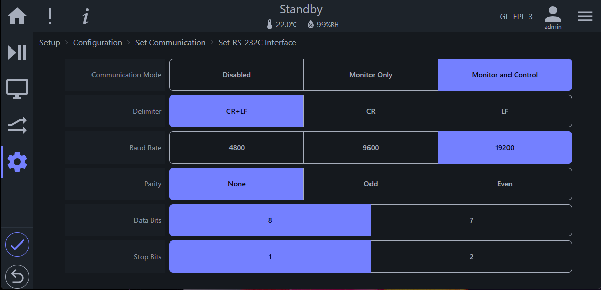
RS-232C (Recommended Standard-232) is a serial interface widely adopted for transmission between computers and peripheral devices. It is based on a communication standard of the EIA. If this communication type is available on your GL controller system, it is enabled via the Service menu (a menu only available to ESPEC service technician or engineer). The setting requires specific baud rate and data transmission parameters as depicted below.
The following figure depicts settings for address and delimiter for RS-23 2C communication, displayed in the legacy setup screen, being used here for clarity purposes only.
Procedure:
-
Select “Set RS-232C Interface” under the Set Communication page.
-
Set the delimiter and transmission rate. After completing the settings, return to the Monitor Screen.
Note: The difference between RS232C and RS485 is the addressing. The default address used by RS485 is 1, while RS232C does not require one. It can be provided in the communication protocol, but it will ignore it.
As stated in Section 1.1.1, the GL controller supports both DHCP and static network configurations. By default, the GL controller uses DHCP to join the network, using an IP address provided by the DHCP server. The IP address used by the GL controller (on a DHCP network) is depicted in the following figure.
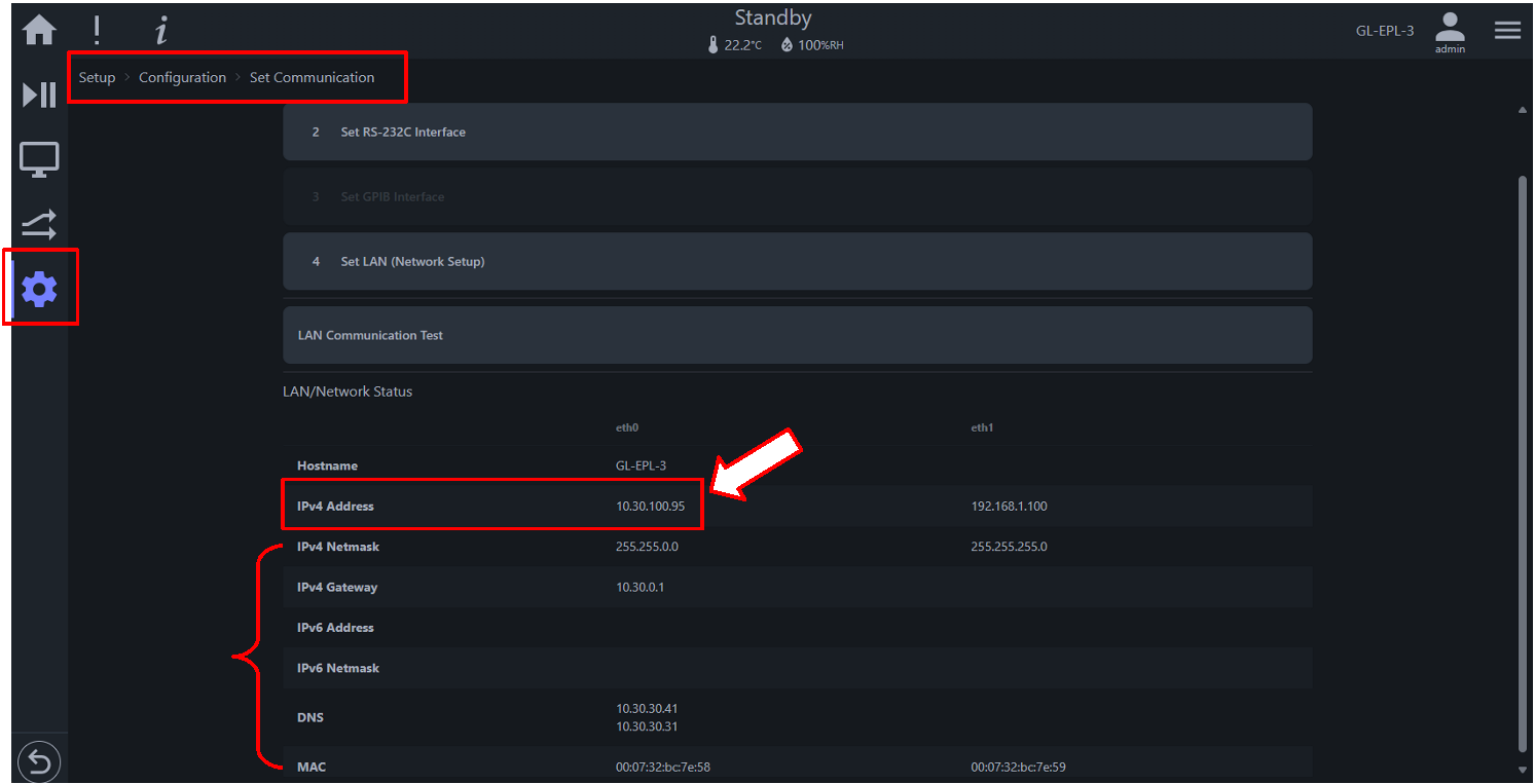
Procedure: How to get to the network status in the above figure
-
At the GL home page on the HMI, press the Setup button or the gear icon in the menu bar on the left.
-
Press Configuration
-
Press Set Communication and scroll down the page if necessary.
The IP address in the red box (referenced by the arrow) is the one provided by the DHCP server and is being used by the GL controller in question. It is illustrated here as an example. If this box displays 192.168.0.83, then the GL controller is using its fallback IP address on a network without DHCP service.
The network setting on the PC that communicates with the GL controller must be configured using the same Class C network protocol with the recommended IP address as follows:
- IP Address: 192.168.0.84
- Subnet Mask: 255.255.255.0
- Gateway: 192.168.0.1
- Preferred DNS server: 8.8.8.8
- Alternate DNS server: 8.8.4.4
As depicted in the following figure, the Set LAN screen displays the DHCP checkbox and the fallback network settings to be used by the GL controller in the absence of a DHCP service.
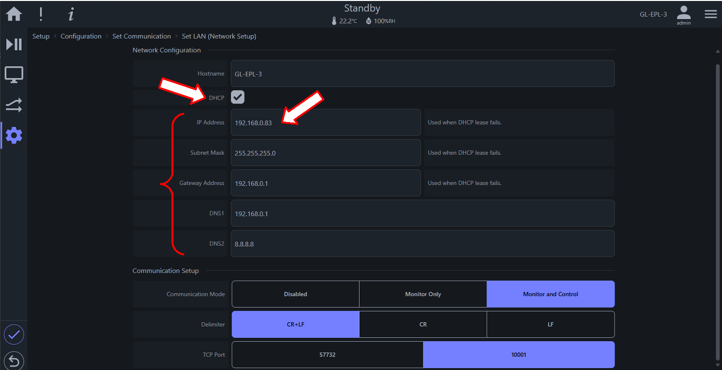
The five fields below the DHCP box can be configured for the GL controller to completely use a static network protocol. The DHCP box must be unchecked in order to use the setting, as depicted in the following figure.

Note: If the DHCP box is unchecked but the fallback network paramters remain unchanged, the GL controller will use 192.168.0.83 as a static network IP address.
The following table provides a breakdown of TCP/IP configuration.
| No. | Name | Description |
|---|---|---|
| 1 | Hostname | Displays the hostname of the GL controller system; it can be used to access the GL controller UI via a Web browser. |
| 2 | DHCP | Protocol option; when DHCP box is checked, IP address provided by DHCP server is used; when unchecked, the GL controller uses a static IP configuration, as shown. |
| 3 | IP Address | Displays the current IP address of the GL controller system |
| 4 | Subnet Mask | Displays the network subnet mask of the system |
| 5 | Gateway | Displays the gateway address for network connection points |
| 6 | DNS1 | Displays the primary Domain Name System, DNS1. |
| 7 | DNS2 | Displays the secondary Domain Name System, DNS2. |
With LAN connection, direct communication with the GL controller via its native text commands can be accomplished remotely that can bypass control on the HMI or the Web browser interface. This type of communication uses this LAN Communication Test page locally on the HMI or remotely on the Web display.
The following figure depicts this type of operation using the LAN Communication Test page (on the GL HMI), under the Set Communication page.

| No. | Name | Description |
|---|---|---|
| 1 | Command Prompt | Issue raw commands here; commands must contain command and delimiter, using the correct syntax of command structure. The prompt supports history; previous commands can be recalled with the up-arrow key for editing and re-invocation. |
| 2 | Response Data | Displays responses returned by the GL controller; previously issued commands may be re-executed (re-invoked) by clicking on it. |
Procedure:
-
Press/click Setup (in the menu bar or main home page); press/click Configuration; press/click Set Communication; press/click LAN Communication Test (see arrow).
-
In the command prompt (see arrow), enter: date? and press Enter; enter: rom? and press Enter; enter: temp? and press Enter. Results are shown as follows.
-
To exit the LAN Communication Test page, access any menu outside of this page.


Operation via the LAN Communication Test page (above) is still performed from within the GL controller on the HMI or the remote Web display. An alternative approach is via a terminal emulator such as Termite or PuTTY launched from a PC on the same network to communicate with the GL controller remotely.
Procedure: Remote control via PuTTY
-
Download the executable or installable package for the desired platform from the PuTTY official web site: https://www.putty.org.
-
Look up the IP address of the GL controller on the Set Communication page, indicated by the IPv4 Address field, under the eth0 column (see arrow).
-
Launch PuTTY on your PC and follow the procedure in the diagram to connect to the GL controller.
- Enter IP address found in (2). Example: 10.30.200.247
- Enter port number 10001 in the "Port" field (in place of default 22)
- Select Raw for connection type
- Click Open to start the communication session
-
Enter "date?" and press Enter; enter "rom?" and press Enter; enter "temp?" and press Enter. Results are shown below.
-
To end communication, click X and confirm the exit.


Direct communication with the GL controller at the text-command level is achievable with the remote TCP or serial communication protocol. The following figure displays the Set Protection page under the Setup menu with two enable options: (i) Monitor Only and (ii) Monitor and Control. If the option is disabled (as depicted in the figure), remote command communication is not possible. Refer to the GL Controller Operation Manual (Section 2.10 and Section 6.5) for details.
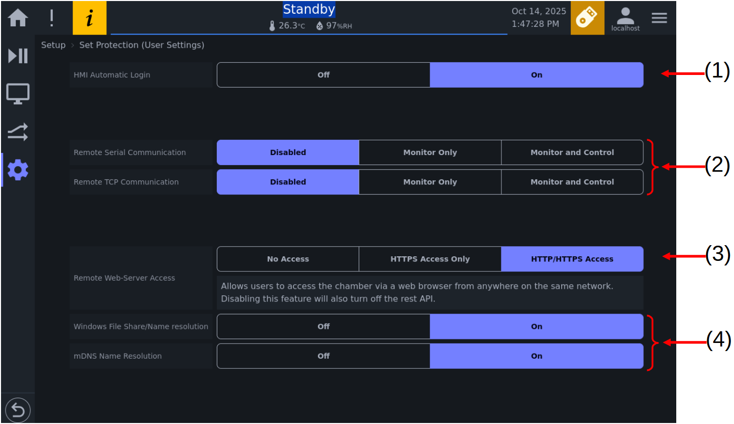
| No. | Description |
|---|---|
| 1 | HMI autologin; User has option to enable or disable HMI auto login as an extra protection. |
| 2 | Remote communication via TCP or serial interface can be controlled with Disabled, Monitor Only, and Monitor and Control options. When disabled, remote communication is blocked; when set to Monitor Only, monitor commands can be issued; when set to Monitor and Control, both monitor and set commands can be issued. |
| 3 | Remote access to the GL controller system with full control and operation via a Web-based device; e.g., access via a Web browser running on PC or handheld device on the local network. |
| 4 | Configuration options for Multicast DNS (mDNS) name resolution on the local network. mDNS provides a quick way to resolution hostname on the local network; access to a device via its hostname need only include the dot local (.local) attached to the target hostname. This option is secondary to No. 3. |
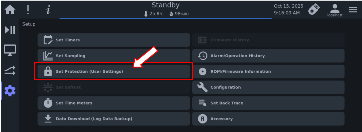
By default, the GL controller uses TCP for remote communication. If remote serial communication is desired and it is available as an optional feature on your GL controller system, it can be set via the appropriate button.
Procedure:
-
Log in as user with administrative privilege; the localhost user that the system uses is a viable option.
-
Access the Home page and press Set Protection (User Settings) (see arrow).
Note: If this button is not available, select Setup (in the menu bar), then press the Set Protection (User Settings) button (see arrow).
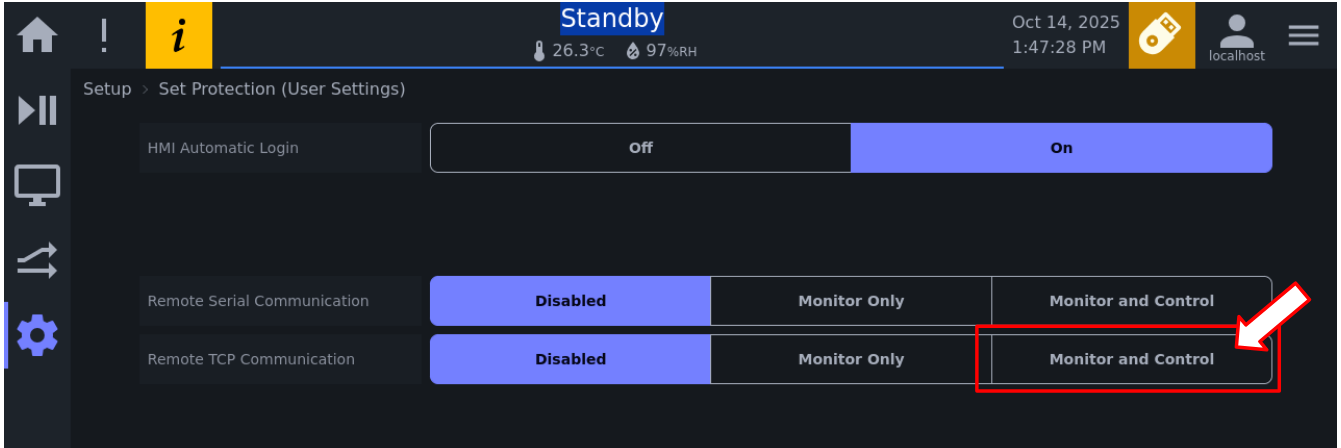
-
Press the Monitor and Control button in the Remote TCP Communication field (see arrow)
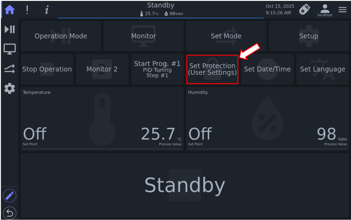
Section 2.1.5 of this manual provides details on how to use remote TCP communication via an SSH terminal emulator, called PuTTY.
This chapter explains the application process and procedure of setting commands and monitor commands. Examples are included to demonstrate their application.
The monitor and setting commands are shown in the following two tables, respectively. The following is a list of monitor commands for GL controller.
Table 3.1: List of monitor commands.
| Monitor Command | Description |
|---|---|
| MODE? | Monitors the operation mode |
| MON? | Monitors the operation state |
| TEMP? | Monitors information related to the temperature |
| HUMI? | Monitors information related to the humidity |
| SET? | Monitors information related to the refrigerator setting |
| REF? | Monitors the output state of the refrigerator |
| RELAY? | Monitors the time signal setting |
| %? | Monitors the heater output control |
| EQUI MON? | Device (Equipment) setting monitor |
| CONSTANT SET? | Monitors the constant mode setting |
| RUN PRGM MON? | Monitors the operation state of the remote program that is operating |
| RUN PRGM? | Monitors the settings of the remote program that is operating |
| PRGM MON? | Monitors the operation state of the program that is operating |
| PRGM SET? | Monitors the end setting, etc., of the program that is operating |
| PRGM DATA? | Monitors the details of the program number |
| PRGM USE? | Monitors the number of set program numbers |
| ALARM? | Monitors information related to alarms |
| KEYPROTECT? | Monitors the protection setting |
| TYPE? | Monitors the chamber information |
| ROM? | Monitors the ROM version |
| MASK? | Monitors the interruption mask setting |
| SRQ? | Monitors the interruption status |
| DATE? | Monitors the date of the internal calendar |
| TIME? | Monitors the current time of the internal calendar |
| TIMER LIST? | Monitors the timer setting information |
| TIMER ON? | Monitors the number of the timer enabled for startup |
| TIMER USE? | Monitors the number of the set timer |
| SYSTEM SET? | Monitors the on-board specimen temperature information |
| MON PTC? | Monitors the operation state (including specimen temperature information) |
| SET PTC? | Monitors the specimen temperature control that is operating |
| PTC? | Monitors the specimen temperature control parameters |
| PRGM DATA PTC? | Monitors the details of the program number (including specimen temperature information) |
| AIS? | Chamber information monitor for automatic inspection |
Note: The question mark (?) attached to each command indicates a status request. It is part of the command; a syntax error message (CMD_ERR) will occur without it.
The following table provides a list of the GL controller setting commands, listed in order based on operating settings, program operation settings, and administrative settings.
Table 3.2: List of settings commands.
| Setting Command | Description |
|---|---|
| POWER | Turns the panel power ON/OFF. |
| TEMP | Configures settings related to the temperature. |
| HUMI | Configures settings related to the humidity. |
| SET | Sets the refrigerator. |
| RELAY | Sets the time signal. |
| MODE | Sets the operation state. |
| CONSTANT SET | Constant value mode setting |
| RUN PRGM | Sets and starts remote program operation. |
| PRGM | Controls the program that is operating. |
| PRGM DATA WRITE | Edits the program data. |
| PRGM ERASE | Deletes the program data. |
| KEYPROTECT | Sets protection. |
| MASK | Performs the mask setting of the SRQ status. |
| SRQ | Clears the SRQ status. |
| DATE | Changes the date of the internal calendar. |
| TIME | Changes the time of the internal calendar. |
| TIMER WRITE | Sets the timer. |
| TIMER ERASE | Deletes the timer setting. |
| TIMER | Starts the timer. |
| TEMP PTC | Configures settings related to the specimen temperature in constant mode. |
| PTC | Sets the specimen temperature control parameters. |
Note: The GL controller system does not have a panel power supply key, and there is no "panel power supply OFF" operation. In general-purpose communication, "screen off and standby state" is treated as "panel power supply OFF." The "POWER" command in the table above is listed as a legacy command.
Monitor commands follow the format as described in Section 1.3. In the following description, spaces and quotation marks ("") are used to highlight certain areas and specific commands, respectively.
ROM version monitor
| Main command | Option command | Detailed Descriptions |
|---|---|---|
| ROM? | - |
Description: Returns the version of the ROM for the temperature control unit of the chamber. Monitor command example: "ROM?" Response data format: "ROM type ROM version" Response example: "GL-ENA 3.4.0" |
| DISP |
Description: Returns the version of the ROM for the display unit of the chamber. *Monitor command example: "ROM?, DISP" Response data format: "ROM type ROM version" Response example: "GL-ENA 4.0.0" |
|
| CONT |
Description: Returns the version of the ROM for the temperature control unit of the chamber. Monitor command example: "ROM?, CONT" Response data format: "ROM type ROM version" Response example: "GL-ENA 3.4.0" |
Date monitor
| Main command | Option command | Detailed Descriptions |
|---|---|---|
| DATE? | - |
Description: Returns the date of the internal calendar. Monitor command example: "DATE?" Response data format: "Year.Month/Day" Response example: "25.06/09" |
Time monitor
| Main command | Option command | Detailed Descriptions |
|---|---|---|
| TIME? | - |
Description: Returns the current time of the internal calendar. Monitor command example: "TIME?" Response data format: "Hour:Minute:Second" Response example: "18:00:00" |
Interrupt information monitor
| Main command | Option command | Detailed Descriptions |
|---|---|---|
| SRQ? | - |
Description: Returns the state of the SRQ status. Monitor command example: "SRQ?" Response data format: "SRQ1 SRQ2 SRQ3 SRQ4 SRQ5 SRQ6 SRQ7 SRQ8" Response example: "01000000" SRQ1: Not used SRQ2: When an alarm occurs on the chamber, 1 is set. SRQ3: When a single-step operation ends in remote program mode, 1 is set. SRQ4: When the state transitions from power off to operation, or vice versa, 1 is set. SRQ5: Not used SRQ6: Not used SRQ7: Reserved with the SRQ function for GPIB communication SRQ8: Not used (Caution)
|
Interrupt mask monitor
| Main command | Option command | Detailed Descriptions |
|---|---|---|
| MASK? | - |
Description: Returns the value of the mask interruption status setting bit (the value will be 0 or 1). Monitor command example: "MASK?" Response data format: "mask setting bit value" Response example: "1" For bit allocations, see the "SRQ?" monitor command. |
Valid timer monitor
| Main command | Option command | Detailed Descriptions |
|---|---|---|
| TIMER ON? | - |
Description: Returns the number of valid timers and the timer number. Monitor command example: "TIMER ON?" Response data format: "number-of-valid-timers [,timer-number] [,timer-number]" Response example: "0" |
Timer usage monitor
| Main command | Option command | Detailed Descriptions |
|---|---|---|
| TIMER USE? | - |
Description: Returns the number of set timers and the timer number. Monitor command example: "TIMER USE?" Response data format: "number-of-set-timers [,timer-number] [,timer-number]" Response example: "2,0,1" |
Timer content monitor
| Main command | Option command | Detailed Descriptions |
|---|---|---|
| TIMER LIST? | 0 |
Description: Returns the settings of the quick timer. Monitor command example: "TIMER LIST?,0" Response data format: "operation-mode ,set-time" or "stop-mode ,set-time" Response example: For details about operation mode and stop mode, see Table 3.4 and Table 3.5. Returns "NA:DATA NOT READY" when timer data is not set. |
| 1 |
Description: Returns the settings of timer 1 (start timer). Monitor command example: "TIMER LIST?, 1" Response data format: "timer-number ,start-mode ,operation-mode" Response example: For details about start mode and operation mode, see Table 3.3 and Table 3.4. Returns "NA:DATA NOT READY" when timer data is not set. |
|
| 2 |
Description: Returns the settings of timer 2 (start timer). Monitor command example: "TIMER LIST?, 2" Response data format: "timer-number ,start-mode ,operation-mode" Response example: For details about start mode and operation mode, see Table 3.3 and Table 3.4. Returns "NA:DATA NOT READY" when timer data is not set. |
Table 3.3 Start mode details
| Setting | Response data display | Response example |
|---|---|---|
| First execution mode | "MODE 1, start-date,start-time" | "MODE 1,25.03/04,10:00" |
| Weekly execution mode | "MODE 2,start-day,start-time" | "MODE 2,SAT,23:00" |
| Daily execution mode | "MODE 3,start-time" | "MODE 3,0:00" |
The start days are expressed as follows. Monday: "MON"; Tuesday: "TUE" ; Wednesday: "WED"; Thursday: "THU"; Friday: "FRI"; Saturday: "SAT"; Sunday: "SUN".
Table 3.4 Operation mode details
| Setting | Response data display | Response example |
|---|---|---|
| Program operation | "RUN, program-number,step-number" | "RUN,RAM:1,STEP1" |
| Constant operation | "CONSTANT" | "CONSTANT" |
Note: The program numbers are expressed as follows: "RAM:1" to "RAM:xx", where x is the slot number of the program stored on the GL controller system.
Table 3.5 Stop mode details
| Setting | Response data display | Response example |
|---|---|---|
| All operation stopped | "STANDBY" | "STANDBY" |
| Panel power off | "OFF" | "OFF" |
Alarm status monitor
| Main command | Option command | Detailed Descriptions |
|---|---|---|
| ALARM? | - |
Description: Returns the number of occurring alarms and the alarm number. Monitor command example "ALARM?" Response data format "number-of-alarms [,alarm-number] [,alarm-number]..." Response example "2,1,7"
|
Key protection monitor
| Main command | Option command | Detailed Descriptions |
|---|---|---|
| KEY PROTECT? | - |
Description: Returns the key protection state. Monitor command example: "KEY PROTECT?" Response data format: "key-protection-state" Response example: "ON"
|
Note: This command is recognized and accepted by the GL controller as a single- or double-word command; i.e., "KEYPROTECT?" or "KEY PROTECT?".
Chamber type monitor
| Main command | Option command | Detailed Descriptions |
|---|---|---|
| TYPE? | - |
Description: Returns the type of sensor connected to the temperature controller, the type of temperature controller, and the set temperature upper limit. Monitor command example: "TYPE?" Response data format: "dry-bulb-sensor-type[, wet-bulb-sensor-type], temperature-controller-type, set-temperature-upper-limit" Response example: "T, T, GL, 185.0"
|
Operation mode monitor
| Main command | Option command | Detailed Descriptions |
|---|---|---|
| MODE? | - |
Description: Returns the chamber operation state. Monitor command example: "MODE?" Response data format: "operation-state" Response example: "CONSTANT"
|
| DETAIL |
Description: Returns the (detailed) chamber operation state. Monitor command example: "MODE?, DETAIL" Response data format: "operation-state" Response example: "CONSTANT"
|
|
| Test area state monitor |
| Main command | Option command | Detailed Descriptions |
|---|---|---|
| MON? | - |
Description: Returns the chamber test area state. Monitor command example: "MON?" Response data format: "measured-temperature, [measured-humidity] ,operation-mode, number-of-alarms-occurring" Response example: "21.9, 0, STANDBY, 0"
|
| DETAIL |
Description: Returns the (detailed) chamber operation state. Monitor command example: "MON?, DETAIL" Response data format:"measured-temperature, [measured-humidity] ,operation-mode, number-of-alarms-occurring" Response example: "21.9, 0, STANDBY, 0"
|
Temperature setting monitor
| Main command | Option command | Detailed Descriptions |
|---|---|---|
| TEMP? | - |
Description: Returns the temperature parameter. Monitor command example: "TEMP?" Response data format: "measured-temperature ,temperature-set-point ,temperature-upper-limit-alarm-value ,temperature-lower-limit-alarm-value" Response example: "23.0, 85.0, 105.0, -75.0"
|
Humidity setting monitor
| Main command | Option command | Detailed Descriptions |
|---|---|---|
| HUMI? | - |
Description: Returns the humidity parameter. Monitor command example: "HUMI?" Response data format: "measured-humidity,humidity-set-point,humidity-upper-limit-alarm-value,humidity-lower-limit-alarm-value" Response example: "10.3, 10.0, 100.0, 0.0" Note: If humidity feature is not available or turned OFF, the response is: 0.0, OFF, 100.0, 0.0"
|
Refrigeration capacity setting monitor
| Main command | Option command | Detailed Descriptions |
|---|---|---|
| SET? | - |
Description: Returns the refrigeration capacity set point of the chamber. Monitor command example: "SET?" Response data format: "refrigeration-capacity-set-point" Response example: "REF9" "Refrigeration-capacity-set-point" has the following response, according to the refrigeration capacity set point.
|
Refrigeration output monitor
| Main command | Option command | Detailed Descriptions |
|---|---|---|
| REF? | - |
Description: Returns the number of equipped refrigerators and their operation state. Monitor command example: "REF?" Response data format: "number-of-equipped-refrigerators, operation-state-of-refrigerator-1[, operation-state-of-refrigerator-2]" Response example: "2, OFF1, OFF2" or "1, ON1" The refrigerator "operation-state" has the following response.
|
Relay or Time Signal monitor
| Main command | Option command | Detailed Descriptions |
|---|---|---|
| RELAY? | - |
Description: Returns the number of enabled relay contact outputs and their numbers. Monitor command example: "RELAY?" Response data format: "number-of-enabled-relays, [relay-number, relay-number,relay-number]..." Response example: "2,1,2" |
Heater output monitor
| Main command | Option command | Detailed Descriptions |
|---|---|---|
| %? | - |
Description: Returns the number of controllable heaters and their heater output values. Monitor command example: "%?" Response data format: "number-of-heaters, heater-output-value[,humidifying-heater-output-value]" Response example: "2, 73.1, 0.0"
|
Constant monitor
With the GL controller, the monitor command "CONSTANT SET?" has extensive optional parameters to probe and list the setting parameters (or values) in all three Constant setups (namely, Constant 1, 2 and 3). If the command is issued without the Constant number, Constant 1 will be used. Descriptions and examples of the use of this command and its parameters are listed as follows.
| Main command | Option | Parameter | Detailed Descriptions |
|---|---|---|---|
| CONSTANT SET? | 1 | TEMP |
Description: Returns the temperature setting in constant mode (No. 1). Monitor command example: "CONSTANT SET?, 1, TEMP" Response data format: "temperature setting value of Constant 1, control permission" Response example: "85.0, ON"
|
| 1 | HUMI |
Description: Returns the humidity set point in constant mode (No. 1). Monitor command example: "CONSTANT SET?, 1, HUMI" Response data format: "humidity-setpoint of Constant No. 1, control-permission" Response example: "80, ON"
|
|
| 1 | REF |
Description: Returns the refrigerator setting in constant mode (No. 1). Monitor command example: "CONSTANT SET?, 1, REF" Response data format: "Refrigerator setting" Response example: "AUTO" The refrigerator setting varies depending on the number of equipped refrigerators and the auto/manual settings.
|
|
| 1 | RELAY |
Description: Returns the relay set point in constant mode (No. 1). Monitor command example: "CONSTANT SET?, 1, RELAY" Response data format: "number-of-enabled-relays [,relay-number] [,relay-number]..." Response example: "2, 1, 2" or "0" The target is the relay output selected as the time signal option. |
Program execution monitor
| Main command | Option command | Detailed Descriptions |
|---|---|---|
| PRGM MON? | - |
Description: Returns the operation state parameter when a program is operating. Monitor command example: "PRGM MON?" Response data format: "step-number-being-executed, temperature-set-point[, humidity-set-point], remaining-time, remaining-counter-A, remaining-counter-B" Response example: "1, 23.0, 50.0, 01:59, 0, 0"
|
| EXT1 |
Description: Returns the operation state parameter when a program is operating. Monitor command example: "PRGM MON?, EXT1" Response data format: "step-number-being-executed, temperature-set-point[, humidity-set-point], remaining-time, remaining-counter-A, remaining-counter-B" Response example: "1, 80.0, OFF, 00:30:00, 9, 0" Note: The "EXT1" option in the command returns hours:minutes:seconds formats.
|
Program assignment monitor
| Main command | Option command | Detailed Descriptions |
|---|---|---|
| PRGM SET? | - |
Description: Returns information with program location, program name and end setting, etc., of the program operation being executed. Monitor command example: "PRGM SET?" Response data format: "program-location, program-name, end-condition" Response example: "RAM:6, Humidity Fluctuation, END(STANDBY)"
|
Report locations of programs on the system
| Main command | Option command | Detailed Descriptions |
|---|---|---|
| PRGM USE? | - |
Description: Returns the location (slot numbers) of program currently stored on the system. Monitor command example: "PRGM USE?" Response data format: "program-location-slot-number" Response example: "46, 3, 1, 2, 4, 5, 8, 9, 10, 12, 14, 20, 41, 44, 45, 46"
|
| RAM: slot number |
Description: Returns the program name of the specified program number and the edit or creation date. Monitor command example: "PRGM USE?, RAM:46" Response data format: "program-name,creation-date" Response example: "PAUL3LOOPS, 25.08/08"
|
Program data monitor
Program data command "PRGM DATA?" offers several separate parameters to specify the details of the listed program. These are: "PRGM DATA?, RAM:#"; "PRGM DATA?, RAM:#, STEP#"; "PRGM DATA?, RAM:#, DETAIL"; "PRGM DATA?, RAM:#, EXT1"; "PRGM DATA?, RAM:#, CONSTANT". Note: Both "PRGM DATA?, RAM:#, EXT1" and "PRGM DATA?, RAM:#, CONSTANT" are equivalent. These commands are outlined as follows.
| Main command | Option command | Detailed Descriptions |
|---|---|---|
| PRGM DATA? | RAM: program number |
Description: Returns the details of the specified program number (slot number). Monitor command example: "PRGM DATA?, RAM:23" Response data format: "number-of-steps, program-name, counter-A-setting,counter-B-setting, end-condition" Response example: "10, < PAUL CNTR3 >, COUNT, A(1.3.1), B(3.6.1), END(STANDBY)"
|
| RAM: program number, STEPxx |
Description: Returns the information of the specified step data. Monitor command example: "PRGM DATA?, RAM:23, STEP1" Response data format: "step-number, temperature-set-point, temperature-gradient [, humidity-set-point, humidity-gradient], time-setting, exposure-setting, refrigerator-setting[, time-signal-setting], paused-setting " Response example: "1, TEMP30.0, TEMP RAMP OFF, HUMIOFF, HUMI RAMP OFF, TIME00:02, GRANTY OFF, REF9, RELAY ON, PAUSE OFF"
|
|
| RAM: program number, DETAIL |
Description: Returns the step information of the specified program pattern. Monitor command example: "PRGM DATA?, RAM:23, DETAIL" Response data format: "temperature-warning-upper-limit-absolute-value, temperature-warning-lower-limit-absolute-value [, humidity -warning-upper-limit-absolute-value] [,humidity -warning-lower-limit-absolute-value] temperature-start-setting [, start-temperature-setting] [, humidity-start-setting] [, start-humidity-setting]" Response example: "185.0, -75.0, 100, 0, TEMPOFF, HUMIOFF"
|
Specimen temperature information monitor
| Main command | Option command | Detailed Descriptions |
|---|---|---|
| SYSTEM SET? | PTS |
Description: Returns the on-board information of the specimen temperature monitor function. Monitor command example: "SYSTEM SET?, PTS" Response data format: "On-board-information" Response example: "MON"
|
| PTC |
Description: Returns the on-board specimen temperature information. Monitor command example: "SYSTEM SET?, PTC" Response data format: "On-board-information" Response example: "ON"
|
|
| PTCOPT |
Description: Returns the on-board specimen temperature information. Monitor command example: "SYSTEM SET?, PTCOPT" Response data format: "On-board-information" Response example: "MC"
|
Test area state monitor with detail of specimen information
| Main command | Option command | Detailed Descriptions |
|---|---|---|
| MON PTC? | - |
Description: Returns the chamber test area state (including specimen temperature control). Monitor command example: "MON PTC?" Response data format: "specimen-temperature, measured-temperature, [measured-humidity] ,operation-mode, alarm-number" Response example: "100.3, 102.2, 50, CONSTANT, 0"
|
Monitor specimen control temperature settings
| Main command | Option command | Detailed Descriptions |
|---|---|---|
| TEMP PTC? | - |
Description: Returns the chamber test area state (including specimen temperature control). Monitor command example: "TEMP PTC?" Response data format: "specimen-temperature, measured-temperature, [measured-humidity] ,operation-mode, alarm-number" Response example: "OFF, 999.9, 999.9, OFF, OFF, OFF, OFF"
|
Operating specimen temperature control monitor
| Main command | Option command | Detailed Descriptions |
|---|---|---|
| SET PTC? | - |
Description: Returns the specimen temperature control state. Monitor command example: "SET PTC?" Response data format: "specimen-temperature-control-status,maximum-deviation-for-specimen-temperature-control,minimum-deviation-for-specimen-temperature-control" Response example: "ON, 20.0, -20.0"
|
Specimen temperature control parameter monitor
| Main command | Option command | Detailed Descriptions |
|---|---|---|
| PTC? | - |
Description: Returns the setting parameter related to specimen temperature control. Monitor command example: "PTC?" Response data format: "upper-limit, lower-limit, P-parameter, filter-value, I-parameter, option-setting-1, option-setting-2" Response example: "150.0, -40.0, 1.0, 36.0, 2.0, 0.0, 0.0"
|
Program data monitor with temperature detail
| Main command | Option command | Detailed Descriptions |
|---|---|---|
| PRGM DATA PTC? | RAM: Program number |
Description: Returns the details of the specified program slot number, including specimen temperature control information. Monitor command example: "PRGM DATA PTC?, RAM:23" Response data format: "number-of-steps, program-name, counter-A-setting, counter-B-setting, end-condition" Response example: "10, , COUNT, A(1.3.1), B(3.6.1), END(STANDBY)"
|
| RAM: Program number, STEPxx |
Description: Returns the step information of the specified program pattern. Monitor command example: "PRGM DATA PTC?, RAM:23, STEP1" Response data format: "step-number, temperature-set-point, temperature-gradient, specimen-temperature-status[,humidity-set-point, humidity-gradient], time-setting, soak-time-control-setting [, refrigerator-setting] [, enabled-external-output-setting], paused-setting, maximum deviation, minimum deviation" Response example: "1, TEMP30.0, TEMP RAMP OFF, PTC OFF, HUMIOFF, HUMI RAMP OFF, TIME00:02, GRANTY OFF, REF9, RELAY ON, PAUSE OFF, DEVP10.0, DEVN-10.0"
|
|
| RAM: Program number, DETAIL |
Description: Returns the step information of the specified program number. Monitor command example: "PRGM DATA PTC?, RAM:23, DETAIL" Response data format: "temperature-warning-upper-limit-absolute-value, temperature-warning-lower-limit-absolute-value [, temperature-warning-upper-limit-absolute-value] [, temperature-warning-lower-limit-absolute-value] temperature-start-setting [, start-temperature-setting] [, humidity-start-setting] [, start-humidity-setting]" Response example:"185.0, -75.0, 100, 0, TEMPOFF, HUMIOFF"
|
Remote program operation state monitor
| Main command | Option command | Detailed Descriptions |
|---|---|---|
| RUN PRGM MON? | - |
Description: Returns the operation state of the remote program operation being executed. Monitor command example: "RUN PRGM MON?" Response data format: "data-count, set-temperature [,set-humidity], remaining-time, remaining-repeat-cycles" Response example: "3, 60.0, 10, 01:35, 1"
|
Remote program data monitor
| Main command | Option command | Detailed Descriptions |
|---|---|---|
| RUN PRGM? | - |
Description: Returns the setting data of the remote program operation being executed. Monitor command example: "RUN PRGM?" Response data format: "start-temperature-setting endpoint-temperature-setting [start-humidity-setting endpoint-humidity-setting] time-setting refrigerator-setting [time-signal-setting]" Response example: "TEMP25.0 GOTEMP60.0 HUMI65 GOHUMI10 TIME2:00 REF9"
|
Chamber automatic inspection of system information
The command for automatic inspection of system information (AIS) comes with several optional parameters to specifically probe and list information of the right component. The optional parameter "UNIT" can probe and list the number of refrigerator(s) and their type installed. The "TEMP" parameter lists the temperature of the refrigerator circuit. Additional parameters are: "ELV", "FREQ", "REF", "VER", "PRESS". The following table outlines the use of the "AIS" command and its parameters.
| Main command | Option | Parameter | Detailed Descriptions |
|---|---|---|---|
| AIS? | UNIT |
Description: Returns the refrigerator installation information. Monitor command example: "AIS?, UNIT" Response data format: "Number of units installed, type of refrigerator No. 1, type of refrigerator No. 2, type of refrigerator No. 3, type of refrigerator No. 4" Response example: "3, 20, 21, 0, 0"
|
|
| 1 | TEMP |
Description: Returns the temperature of the refrigerator circuit number. Monitor command example: "AIS?, 1, TEMP" Response data format: "refrigeration circuit temperature 1, refrigeration circuit temperature 2, refrigeration circuit temperature 3, refrigeration circuit temperature 4, refrigeration circuit temperature 5" Response example: "0.0,-106.3,0.0,999.9,999.9"
|
|
| ALL | TEMP |
Description: Returns the temperature of all the refrigerator circuit number(s). Monitor command example: "AIS?, ALL, TEMP" Response data format: "refrigeration circuit temperature 1, refrigeration circuit temperature 2, refrigeration circuit temperature 3, refrigeration circuit temperature 4, refrigeration circuit temperature 5", etc. Response example: "returns specifications of all refrigerator circuits. The number of refrigerator circuit may be used to probe the configuration. |
|
| 1 | ELV |
Description: Returns the ELV pulse set point value for controlling the refrigerator. Monitor command example: "AIS?, 1, ELV" Response data format: "Main circuit control ELV setpoint" Response example: "200"
|
|
| 1 | FREQ |
Description: Returns the frequency output value for the inverter board control for refrigerator control . Monitor command example: "AIS?, 1, FREQ" Response data format: "Frequency output value" Response example: "80.0"
|
|
| 1 | REF |
Description: Returns the refrigerator type, refrigerator circuit temperature, ELV pulse setpoint, and frequency output value of the specified refrigerator. Monitor command example: "AIS?, 1, REF" Response data format: "`By refrigerator type, refrigeration circuit temperature 1, refrigeration circuit temperature 2, refrigeration circuit temperature 3, refrigeration circuit temperature 4, refrigeration circuit temperature 5," Response example: "20,0.0,-106.3,0.0,999.9,999.9,200,-99.9"
|
|
| VER |
Description: Returns the version compatible with the automatic inspection system. Monitor command example: "AIS?, VER" Response data format: "Version number" Response example: "1"
|
||
| 1 | PRESS |
Description: Returns the pressure for the refrigerator circuit. Monitor command example: "AIS?, 1, PRESS" Response data format: "refrigeration circuit pressure 1, refrigeration circuit pressure 2, refrigeration circuit pressure 3, refrigeration circuit pressure 4, refrigeration circuit pressure 5" For details, see the "Freezing temperature and pressure information by freezing unit" sheet. Response example: "-0.231,9.999,9.999,9.999,9.999"
|
Equipment setting monitor
| Main command | Option command | Detailed Descriptions |
|---|---|---|
| EQUIMON? | REF |
Description: Returns the effective refrigerator setpoint information. Monitor command example: "EQUIMON?, REF" or "EQUI MON?, REF" Response data format: "refrigerator mode [, refrigerator 1 manual setpoint] [, refrigerator 2 manual setpoint] [, refrigerator 3 manual setpoint] [, refrigerator 4 manual setpoint]" Response example: "AUTO"
|
| FAN |
Description: Returns the active air circulator setpoint information. Monitor command example: "EQUIMON?, FAN" Response data format: "airflow setpoint" Response example: "2"
|
|
| AUXHUMI |
Description: Returns the active auxiliary humidification setpoint. Monitor command example: "EQUIMON?, AUXHUMI" Response data format: "Auxiliary humidification setpoint" Response example: "2"
|
Setting commands have the following command syntax and format:
address,main-command[,option-parameter],setting-data
Quotation marks (" ") used in the sample commands outlined in the description column are to highlight the actual commands issued to the GL controller; spaces within the commands are for readability as well as for normal text printing (allowing word wrapping) on this page. Note: Some commands may not be accepted depending on the chamber. See Table 3.11 Reception for details. In constant operation only constant setup No. 1 is specified.
Date setting
Note: The DATE set command is currently disabled.
| Main command | Option parameter | Transmission data | Detailed Descriptions |
|---|---|---|---|
| DATE | - | Date data |
Description: Set the date Transmission data format: "Year.Month/Day" Setting command example: "DATE, 25.08/04"
|
Time setting
Note: The TIME set command is currently disabled.
| Main command | Option parameter | Transmission data | Detailed Descriptions |
|---|---|---|---|
| TIME | - | Time data |
Description: Sets the time. Transmission data format: "Hour:Minute:Second" Setting command example: "TIME, 18:00:00"
|
Interrupt mask setting
| Main command | Option parameter | Transmission data | Detailed Descriptions |
|---|---|---|---|
| MASK | - | Mask data |
Description: Sets the interrupt mask. Transmission data format: "SRQ1 SRQ2 SRQ3 SRQ4 SRQ5 SRQ6 SRQ7 SRQ8"
|
SRQ status setting
| Main command | Option parameter | Transmission data | Detailed Descriptions |
|---|---|---|---|
| SRQ | - | Reset command |
Description: Clears the SRQ status. Transmission data format: "Reset command" Setting command example: "SRQ,RESET" |
Timer writing
| Main command | Option parameter | Transmission data | Detailed Descriptions |
|---|---|---|---|
| TIMER WRITE | No. 0 | Timer data |
Description: Edits the quick timer. Transmission data format: "start-time, operation-mode" or "start-time, stop-mode" Setting command example: "TIMER WRITE, NO0, 10:00, CONSTANT"
|
| No. 1 | Timer data |
Description: Edits the start timer. Transmission data format: "start-mode, operation-mode" Setting command example: "TIMER WRITE, NO1, MODE1, 25.10/04, 10:00, CONSTANT"
|
|
| No. 2 | Timer data |
Description: Edits the end timer. Transmission data format: "start-mode, stop-mode" Setting command example: "TIMER WRITE, NO2, MODE2, SAT, 10:00, OFF"
|
Note: The timer setpoint will be saved, but the timer will not be in reservation state. To set the timer to reservation state, the "TIMER" command is required. If the timer to be written to is in a reserved state, the change request will not be accepted; an error will occur. Error message: "NA: CHB NOT READY". You can set each timer (quick timer, start timer, end timer) regardless of the timer number. Even if a different timer is registered, a timer will be set.
Table 3.6 Start mode details
| Setting | Response data display | Response example |
|---|---|---|
| First execution mode | "MODE 1, start-date, start-time" | "MODE 1, 25.03/04, 10:00" |
| Weekly execution mode | "MODE 2, start-day, start-time" | "MODE 2, SAT, 23:00" |
| Daily execution mode | "MODE 3, start-time" | "MODE 3, 0:00" |
The start days are expressed as follows. Monday: "MON"; Tuesday: "TUE" ; Wednesday: "WED"; Thursday: "THU"; Friday: "FRI"; Saturday: "SAT"; Sunday: "SUN".
To include or specify multiple days in the expression, insert a separator (i.e., slash) in between the specified days. For example, the following expression specifies Monday and Saturday: "MODE2,MON/SAT,2300".
Table 3.7 Operation mode details
| Setting | Response data display | Response example |
|---|---|---|
| Program operation | "RUN, program-number,step-number" | "RUN,RAM:1,STEP1" |
| Constant operation (No. 1) | "CONSTANT" | "CONSTANT" |
Note: The program numbers are expressed as follows: "RAM:1" to "RAM:xx", where x is the slot number of the program stored on the GL controller system.
Table 3.8 Stop mode details
| Setting | Response data display | Response example |
|---|---|---|
| All operation stopped | "STANDBY" | "STANDBY" |
| Panel power off | "OFF" | "OFF" |
Timer deletion
| Main command | Option parameter | Transmission data | Detailed Descriptions |
|---|---|---|---|
| TIMER ERASE | NO0 | - |
Description: Deletes the specified timer setting. Transmission data format: - Setting command example: "TIMER ERASE, NO0"
|
| NO1 | - |
Description: Deletes the specified timer setting. Transmission data format: - Setting command example: "TIMER ERASE, NO1"
|
|
| NO2 | - |
Description: Deletes the specified timer setting. Transmission data format: - Setting command example: "TIMER ERASE, NO2"
|
|
| NO0 NO1 NO2 |
- |
Description: Deletes the specified timer setting. Transmission data format: - Setting command example: "TIMER ERASE, NO0,NO1,NO2"
|
Valid timer setting
| Main command | Option parameter | Transmission data | Detailed Descriptions |
|---|---|---|---|
| TIMER | ON | Timer number |
Description: Disables the specified timer. Transmission data format: "timer-number" Setting command example: "TIMER, ON, 1"
|
| OFF | Timer number |
Description: Enables the specified timer. Transmission data format: "timer-number" Setting command example: "TIMER,OFF,2"
|
Key protection setting
| Main command | Option parameter | Transmission data | Detailed Descriptions |
|---|---|---|---|
| KEY PROTECT | - | ON |
Description: Turn on key protection Transmission data format: "ON" Setting command example: "KEYPROTECT, ON"
|
| - | OFF |
Description: Turn off key protection Transmission data format: "OFF" Setting command example: "KEYPROTECT, OFF"
|
Note: "KEYPROTECT" and "KEY PROTECT" commands are equivalent. By specifying "ON" or "OFF", the change of setting protection and the operation protection are both turned ON/OFF, accordingly.
Power ON/OFF
| Main command | Option parameter | Transmission data | Detailed Descriptions |
|---|---|---|---|
| POWER | - | ON |
Description: Turns on the panel power and starts constant operation (No. 1). Transmission data format: "ON" Setting command example: "POWER, ON" Response example: "OK: POWER,ON" Note: Time signals associated with constant No. 1 operation will also be turned on. |
| - | OFF |
Description: Stops operation and turns off the panel power. Transmission data format: "OFF" Setting command example: "POWER, OFF" Response example: "POWER,OFF" Constant No. 1 which was started by the ON operation will be turned off. |
Temperature settings
| Main command | Option parameter | Transmission data | Detailed Descriptions |
|---|---|---|---|
| TEMP | - | S set point |
Description: Changes the temperature set point in constant mode (No. 1). Transmission data format: "S-set-point" Setting command example: "TEMP, S23.0"
|
| - | H set point |
Description: Changes the temperature upper limit alarm value. Transmission data format: "H-set-point" Setting command example: "TEMP, H100.0"
|
|
| - | L set point |
Description: Changes the temperature lower limit alarm value. Transmission data format: "L-set-point" Setting command example: "TEMP, L-40.0"
|
|
| - | S set point H set point L set point |
Description: Changes the temperature set point in constant mode (No. 1), temperature upper limit alarm value, and temperature lower limit alarm value together. Transmission data format: "S-set-point H-set-point L-set-point" Setting command example: "TEMP, S23.0 H100.0 L-40.0" |
Humidity settings
| Main command | Option parameter | Transmission data | Detailed Descriptions |
|---|---|---|---|
| HUMI | - | S set point |
Description: Changes the humidity set point in constant mode (No. 1). Transmission data format: "S-set-point" Setting command example: "HUMI,S85"
|
| - | H set point |
Description: Changes the humidity upper limit alarm value. Transmission data format: "H-set-point" Setting command example: "HUMI, H100"
|
|
| - | L set point |
Description: Changes the humidity lower limit alarm value. Transmission data format: "L-set-point" Setting command example: "HUMI, L0"
|
|
| - | S set point H set point L set point |
Description: Changes the humidity set point in constant mode (No. 1), humidity upper limit alarm value, and humidity lower limit alarm value together. Transmission data format: "S-set-point H-set-point L-set-point" Setting command example: "HUMI, S23 H100 L0"
|
Refrigerator settings
| Main command | Option parameter | Transmission data | Detailed Descriptions |
|---|---|---|---|
| SET | - | set point |
Description: Changes the refrigeration capacity set point in constant mode (No. 1). Transmission data format: "REF-set-point" Setting command example: "SET, REF9"
|
Relay or Time Signal settings
| Main command | Option parameter | Transmission data | Detailed Descriptions |
|---|---|---|---|
| RELAY | ON | Relay number |
Description: Enables the relay set point in constant mode (No. 1). Transmission data format: "relay-number [, relay-number][, relay-number]..." Setting command example: "RELAY,ON,1,2"
|
| OFF | Relay number |
Description: Disables the relay set point in constant mode (No. 1). Transmission data format: "relay-number [, relay-number][, relay-number]..." Setting command example: "RELAY,OFF,1,2"
|
Program operation control
| Main command | Option parameter | Transmission data | Detailed Descriptions |
|---|---|---|---|
| PRGM | RUN | program number, step number |
Description: Starts the specified program number (identified by slot number). Transmission data format: "program-number, start-step-number" Setting command example: "PRGM, RUN, RAM:1, STEP1"
|
| PAUSE | - |
Description: Pauses the program operation that is operating. Transmission data format: - Setting command example: "PRGM, PAUSE"
|
|
| CONTINUE | - |
Description: Restarts the paused program operation. Transmission data format: - Setting command example: "PRGM, CONTINUE"
|
|
| ADVANCE | - |
Description: Ends the step that is operating and operates the next step. Transmission data format: - Setting command example: "PRGM, ADVANCE"
|
|
| END | Condition after program ends |
Description: Ends program operation that is operating at that point, and migrates operation according to the specified end condition. Transmission data format: "end-condition" Setting command example: "PRGM, END, HOLD"
|
Operation mode setting
| Main command | Option parameter | Transmission data | Detailed Descriptions |
|---|---|---|---|
| MODE | - | OFF |
Description: Change the operation state to a specified state (OFF). Transmission data format: "OFF" Setting command example: "MODE, OFF" |
| - | STANDBY |
Description: Change the operation state to standby state. Transmission data format: "STANDBY" Setting command example: "MODE, STANDBY" |
|
| - | CONSTANT, No. |
Description: Change the operation state to a specified constant operating state. Transmission data format: "CONSTANT, Number" Setting command example: "MODE, CONSTANT, 1"
|
|
| - | RUN, No. |
Description: Change the operation state to a specified program operating state. Transmission data format: "RUN program number" Setting command example: "MODE, RUN1"
|
Constant operation setting
The "CONSTANT SET" command has the ability to control all three Constant setup modes, namely, Constant 1, 2, and 3. With that, it is more advantageous than the "TEMP,S/H/L setpoint" (or "HUMI,S/H/L setpoint") command, where by default it affects only Constant 1. In addition, the "CONSTANT SET" command can control other optional devices, such as relay, fan, dehumidification, ref, etc. The following table outlines how the "CONSTANT SET" command is used.
| Main command | Option parameter | Transmission data | Detailed Descriptions |
|---|---|---|---|
| CONSTANT SET | No., TEMP | S set point |
Description: Change fixed value mode of temperature setting. Transmission data format: "temperature setting value" Setting command example: "CONSTANT SET, 1, TEMP, 50.0"
|
| No., HTEMP | H set point |
Description: Change fixed value mode of the absolute upper temperature alarm value. Transmission data format: "temperature setting value" Setting command example: "CONSTANT SET, 1, HTEMP, 90.0"
|
|
| No., LTEMP | L set point |
Description: Change fixed value mode of the absolute lower temperature alarm value. Transmission data format: "temperature setting value" Setting command example: "CONSTANT SET, 1, LTEMP, -5.0"
|
|
| No., HUMI | S set point |
Description: Change fixed value mode of humidity setpoint. Transmission data format: "temperature setting value" Setting command example: "CONSTANT SET, 1, HUMI, 50"
|
|
| No., HHUMI | H set point |
Description: Change fixed value mode of the absolute upper humidity limit alarm value. Transmission data format: "temperature setting value" Setting command example: "CONSTANT SET, 1, HHUMI, 50"
|
|
| No., LHUMI | L set point |
Description: Change fixed value mode of the absolute lower humidity limit alarm value. Transmission data format: "temperature setting value" Setting command example: "CONSTANT SET, 1, LHUMI, 0"
|
|
| No., RELAY | ON, No. |
Description: Change the time signal setpoint in constant mode (set to ON). Transmission data format: "relay number [, relay number] [, relay number]..." Setting command example: "CONSTANT SET, 1, RELAY, ON, 1"
|
|
| No., RELAY | OFF, No. |
Description: Change the time signal setpoint in constant mode (set to ON). Transmission data format: "relay number [, relay number] [, relay number]..." Setting command example: "CONSTANT SET, 1, RELAY, ON, 1"
|
|
| No., REF | REF setpoint |
Description: Change the fixed value mode of the refrigerator setpoint. Transmission data format: "REF, refrigerator setpoint" Setting command example: "CONSTANT SET, 1, REF, REF9"
|
|
| No., REFSET | REFSET setpoint |
Description: Change the fixed value mode of the refrigerator setpoint (detailed specifications). Transmission data format: "REFSET, refrigerator setpoint" Setting command example: "CONSTANT SET, 1, RESET, ##", where "##" is the setpoint decimal value.
|
|
| No., FAN | FAN, airflow setpoint |
Description: Change the fixed value mode of the air circulator airflow setting. Transmission data format: "FAN, air circulator airflow setpoint" Setting command example: "CONSTANT SET, 1, FAN, 2".
|
|
| No., DEHUMI | DEHUMI, dehumidifier setpoint |
Description: Change the fixed value mode of the dehumidifier setpoint. Transmission data format: "DEHUMI, dehumidifier setpoint" Setting command example: "CONSTANT SET, 1, DEHUMI, 1".
|
|
| No., AUXHUMI | AUXHUMI, Auxiliary humi setpoint |
Description: Change the fixed value mode of the auxiliary setpoint. Transmission data format: "AUXHUMI, auxiliary humidifier setpoint" Setting command example: "CONSTANT SET, 1, AUXHUMI, 3".
|
Note: The Constant No. (1, 2, 3) in the option parameter field can be omitted in the above commands. If omitted, Constant No. 1 is specified by default.
Program editing
| Main command | Option parameter | Transmission data | Detailed Descriptions |
|---|---|---|---|
| PRGM DATA WRITE | PGM program slot number | Edit data |
Description: Edits the program data and instructions. Transmission data format: See Table 3.9 Setting command example: "PRGM DATA WRITE, PGM1, EDIT START" "PRGM DATA WRITE, PGM1, STEP1, TEMP10.0, TIME1:00" "PRGM DATA WRITE, PGM1, STEP2, HUMI100, TIME1:00" "PRGM DATA WRITE, PGM1, COUNT, A(1. 2. 10), B(0. 0. 0)" "PRGM DATA WRITE, PGM1, NAME, SAMPLE-1" "PRGM DATA WRITE, PGM1, END, OFF" "PRGM DATA WRITE, PGM1, EDIT END"
|
Note: Editing and/or programming via a direct communication with the GL controller is a delicate matter, which requires every command and action done sequentially and correctly. A command can only be repeated if it was initially entered incorrectly. A successful command already accepted by the GL controller cannot be reentered or an error "NA:INVALID REQ" will occur. If programming sequence is incomplete or a disruption of communication occurred, attempting to reprogram by repeating the program sequence will fail with "NA:INVALID REQ" message. One way to resolve this issue is to restart the GL controller system and re-establish communication. If an error occurs one too many, the "EDIT CANCEL" command can be used to cancel and exit programming editing mode. This command simply ends the current editing and the GL controller exits the editing mode and is ready for the next command. PGM1 refers to program stored in slot 1 or RAM:1. To create and store program in a desired location, include the location number of the program; e.g., PGM15.
The following list outlines details of Program editing and Transmission data details.
-
The following two modes are available for program number editing.
- New mode: Creates new program data. (Step data must be specified continuously from step 1.)
- Overwrite mode: Enables editing of arbitrary step data for program data already created.
-
Use the following procedure to edit program data in new mode.
- Set a create new start request.
- Set the step data for step 1.
- Set the step data for step 2, etc.,
- Set the counter setting (can be omitted).
- Set the file name (can be omitted).
- Set the end condition (can be omitted).
- Set a create new end request.
-
Use the following procedure to edit program data in overwrite mode. Set the overwrite start request.
- Set the step data for the desired step.
- Set the overwrite end request.
-
The following is the description method.
Table 3.9A Transmission Data details
| Setting | Detailed Descriptions | Default value |
|---|---|---|
| New mode Descriptions: New Start | "EDIT START" | |
| New mode Descriptions: New end | "EDIT END" | |
| New mode Descriptions: New cancel | "EDIT CANCEL" | |
| Overwrite Descriptions: Overwrite start | "OVER WRITE START" | |
| Overwrite Descriptions: Overwrite End | "OVER WRITE END" | |
| Overwrite Descriptions: Overwrite cancel | "OVER WRITE CANCEL" |
Table 3.9B Transmission Data and Step Data Descriptions
The setting data is outlined and described in the following table.
| Detailed Descriptions | Default Value |
|---|---|
| "STEPxx,setting-data" | |
| Temperature set point: "TEMPx.x to xxx.x " | 23.0 |
| Temperature gradient: "TRAMPON" or "TRAMPOFF" | 0FF |
| Humidity set point: "HUMIx to xxx" ("HUMI OFF" to turn off) | |
| Humidity gradient: "HRAMPON" or "HRAMPOFF" | OFF |
| Time setpoint: "TIMEx:xx to xxxx:xx" | 0:00 |
| Rate of change setpoint: "TRATE xxx" | - |
| Soak time control setting: "GRANTY ON" or "GRANTY OFF" | GRANT OFF |
| Refrigerator (Freezing) setting: "REFxx" where xx is between 0 and 9 | 9 (auto) |
| Time-signal setting: "RELAY ON x. x…." or "RELAY OFF x. x...." | ALL OFF |
| Pause: "PAUSE ON" or "PAUSE OFF" | OFF |
| Air Circulator airflow setpoint: "FANxx" with xx is "1" to "4" | 4 |
| Dehumidifier setpoint: "DEHUMIxx" xx is "0" and "2" or "9" | 9 |
| Auxiliary humidifier setpoint: "AUXHUMIxx" xx ius "0" to "8" , "9" | 9 |
Note: When a parameter is omitted, the value of the previous step is set; the previous step is set to the default values. A comma may be used to separate each command issued all together. Example: "TEMPxx, TRAMPOFF,TIME1:00". Regarding the time signal settings, if one or more time signal settings are enabled (ON), set the time signal enable setting "ON". If all time signal settings are disabled (OFF), set the time enable setting to "OFF".
Table 3.9C Step Data Descriptions
| Detail Setting | Detailed Descriptions | Omitted Parameter Value |
|---|---|---|
| Counter setting | "COUNT, A(x. x. x)[ , COUNT, B(x. x. x)]" where A(x. x. x) = A(repeat start step number, repeat end step number, number of repeat cycles)
|
0.0.0 |
| File name | "NAME,file-name"
|
PGM-xx |
| Temp upper limit absolute alarm value | "HTEMP,xxxx" | Upper limit of the chamber's allowable range |
| Temp lower limit absolute alarm value | "LTEMP,xxxx" | Lower limit of the chamber's allowable range |
| Humi upper limit absolute alarm value | "HHUMI,xxxx" | Upper limit of the chamber's allowable range |
| Humi lower limit absolute alarm value | "LHUMI,xxxx" | Upper limit of the chamber's allowable range |
| Start condition setting | "PRE MODE, parameter 1, parameter 2", where parameter 1: "TEMP" and "HUMI" can be specified; parameter 2: "OFF", "SV", or "PV" can be specified. Example:
|
OFF |
| Start temperature setting | "PRE TSV,xxx" Can be specified when specifying "temperature setting value" in start setting (if an error occurs, "NA: PARA ERR"). | 23 °C |
| Start humidity setting | "PRE HSV,xxx" Can be specified when specifying "humidity setting value" in start setting (if an error occurs, "NA: PARA ERR"). | 60 %RH |
| Termination condition | "END,end-condition" The end condition following current program completion can take on a number of actions:
|
OFF |
Refer to the section "APPLICATION: EXAMPLES" for details on the use of "PRE MODE" command features.
Deleting program file
| Main command | Option parameter | Transmission data | Detailed Descriptions |
|---|---|---|---|
| PRGM ERASE | RAM: program number | - |
Description Deletes or edits the specified program data. Transmission data format: - Setting command example: "PRGM ERASE, RAM:1"
|
Editing remote program data
| Main command | Option command | Transmission data | Detailed Descriptions |
|---|---|---|---|
| RUN PRGM | - | Program data |
Description: Sets remote program operation. (Remote program operation starts when the setting is completed.) Transmission data format: See Table 3.10. Setting command example: "RUN PRGM, TEMP10.0 GOTEMP23.0 HUMI85 GOHUMI100 TIME1:00"
|
Procedure: Remote program data editing
-
Remote program operation is a one-step program operation that enables control of editing, starting, and ending from the host computer.
-
The command contains a series of controls or settings (see above sample command); once issued, remote program operation commences.
-
When program operation ends, the final settings are retained. *_Note:__ The end condition is not defined in the remote program data.
-
By setting an interrupt mask, the end of remote program operation can be recognized.
-
See the "MASK" setting command or "SRQ?" monitor command.
-
To change the operation state, use the "MODE" or "PRGM" setting command. For example, to change remote operation state to STANDBY, issue "MODE,STANDBY" or "MODE,OFF"; to change remote operation state to CONSTANT, issue "MODE,CONSTANT,1" to start CONSTANT 1; "MODE,CONSTANT,2" to start CONSTANT 2, etc. The "PRGM" setting command can also be used to start a new program from profile.
| Setting | Format | Example |
|---|---|---|
| Start temperature setting | "TEMP" | "TEMP23.0" |
| Endpoint temperature setting (can be omitted) | "GOTEMP" | "GOTEMP30.0" |
| Start humidity setting (can be omitted) | "HUMI" | "HUMI100" ("HUMI OFF" to turn off humidity control) |
| Endpoint humidity setting (can be omitted) |
"GOHUMI" | "GOHUMI50" |
| Time Setting | "TIME" | "TIME99:59" |
| Refrigeration capacity setting (can be omitted) | "REF" | "REF9" |
| Time-signal setting (can be omitted) | "RELAYON" or "RELAYOFF" | "RELAY,1,2" |
Note: If the endpoint temperature (humidity) setting is omitted, the start temperature (humidity) setting is used. If the refrigeration capacity setting or time-signal setting is omitted, the setting for the previous remote program operation is used. (The default refrigeration capacity setting is "REF9", and the default time-signal setting is "OFF" for all.) The order for describing the settings cannot be changed.
Constant mode specimen temperature settings
| Main command | Option command | Transmission data | Detailed Descriptions |
|---|---|---|---|
| TEMP PTC | - | Specimen temperature status Maximum deviation Minimum deviation |
Description: Sets the specimen temperature control set point in constant mode. Transmission data format: "specimen-temperature-status, maximum-deviation, minimum-deviation" Setting command example: "TEMP PTC, PTCON, DEVP10.0, DEVN-10.0"
|
Specimen temperature control parameter settings
| Main command | Option command | Transmission data | Detailed Descriptions |
|---|---|---|---|
| PTC | - | Upper limit, Lower limit, P parameter, Filter value, I parameter, Option setting 1, Option setting 2 |
Description: Sets the specimen temperature control parameters. Transmission data format: "upper-limit, lower-limit, P-parameter, filter-value, I-parameter, option-setting-1, option-setting-2" Setting command example: "PTC, 150.0, -40.0, 1.0, 36.0, 2.0, 0.0, 0.0"
|
Table 3.11 Reception State List
| Main command | Option | A | B | C | D | E | F | G | H | I | J | K | L |
|---|---|---|---|---|---|---|---|---|---|---|---|---|---|
| POWER | ON | 0 | 0 | 0 | 0 | 0 | 0 | 0 | 0 | 0 | 0 | 0 | X |
| OFF | Z | 0 | 0 | 0 | 0 | 0 | 0 | 0 | 0 | 0 | 0 | X | |
| TEMP | Sxxx | 0 | 0 | 0 | 0 | 0 | 0 | 0 | 0 | 0 | 0 | 0 | X |
| Hxxx | 0 | 0 | 0 | 0 | 0 | 0 | 0 | 0 | 0 | 0 | 0 | X | |
| Lxxx | 0 | 0 | 0 | 0 | 0 | 0 | 0 | 0 | 0 | 0 | 0 | X | |
| HUMI | Sxxx | 0 | 0 | 0 | 0 | 0 | 0 | 0 | 0 | 0 | 0 | 0 | X |
| Hxxx | 0 | 0 | 0 | 0 | 0 | 0 | 0 | 0 | 0 | 0 | 0 | X | |
| Lxxx | 0 | 0 | 0 | 0 | 0 | 0 | 0 | 0 | 0 | 0 | 0 | X | |
| SET | 0 | 0 | 0 | 0 | 0 | 0 | 0 | 0 | 0 | 0 | 0 | X | |
| MODE | OFF | 0 | 0 | 0 | 0 | 0 | 0 | 0 | 0 | 0 | 0 | 0 | X |
| STANDBY | 0 | 0 | 0 | 0 | 0 | 0 | 0 | 0 | 0 | 0 | 0 | X | |
| CONSTANT | 0 | 0 | 0 | 0 | 0 | 0 | 0 | 0 | 0 | 0 | 0 | X | |
| RUNxxx | 0 | 0 | 0 | 0 | 0 | 0 | 0 | 0 | 0 | 0 | 0 | X | |
| RUN PRGM | 0 | 0 | 0 | 0 | 0 | 0 | 0 | 0 | 0 | 0 | 0 | X | |
| PRGM | RUN | 0 | 0 | 0 | 0 | 0 | 0 | 0 | 0 | 0 | 0 | 0 | X |
| PAUSE | x | x | x | 0 | x | x | 0 | x | x | 0 | 0 | X | |
| CONTINUE | x | x | x | x | 0 | x | x | 0 | x | 0 | 0 | X | |
| ADVANCE | x | x | x | 0 | 0 | x | x | x | x | 0 | 0 | X | |
| END HOLD | x | x | x | 0 | 0 | Z | 0 | 0 | Z | 0 | 0 | X | |
| END OFF | x | x | x | 0 | 0 | 0 | 0 | 0 | 0 | 0 | 0 | X | |
| END STBY | x | x | x | 0 | 0 | 0 | 0 | 0 | 0 | 0 | 0 | X | |
| END CONST | x | x | x | 0 | 0 | 0 | 0 | 0 | 0 | 0 | 0 | X | |
| PRGM DATA WRITE | 0 | 0 | 0 | 0 | 0 | 0 | 0 | 0 | 0 | 0 | 0 | X | |
| PRGM ERASE | 0 | 0 | 0 | 0 | 0 | 0 | 0 | 0 | 0 | 0 | 0 | X | |
| KEY PROTECT | x | 0 | 0 | 0 | 0 | 0 | 0 | 0 | 0 | 0 | 0 | X | |
| MASK | 0 | 0 | 0 | 0 | 0 | 0 | 0 | 0 | 0 | 0 | 0 | X | |
| SRQ | 0 | 0 | 0 | 0 | 0 | 0 | 0 | 0 | 0 | 0 | 0 | X | |
| DATE | 0 | 0 | 0 | x | x | x | 0 | 0 | 0 | 0 | 0 | X | |
| TIME | 0 | 0 | 0 | x | x | x | 0 | 0 | 0 | 0 | 0 | X | |
| TIMER WRITE | 0 | 0 | 0 | 0 | 0 | 0 | 0 | 0 | 0 | 0 | 0 | X | |
| TIMER ERASE | 0 | 0 | 0 | 0 | 0 | 0 | 0 | 0 | 0 | 0 | 0 | X | |
| TIMER | 0 | 0 | 0 | 0 | 0 | 0 | 0 | 0 | 0 | 0 | 0 | X |
The following table lists the keys (legends) for the preceding table.
| Column Header | Description |
|---|---|
| A | Instrumentation OFF state |
| B | Operation stopped |
| C | Constant operation state |
| D | Program operation state |
| E | Program operation paused |
| F | Program operation end (hold, last setting kept) |
| G | Remote program operation |
| H | Remote operation suspended (paused) |
| I | Remote operation end (hold) |
| J | When change of Setting |
| K | When operation protection is: |
| L | When remote protection is: |
This chapter explains several applications with the communication function by means of flowcharts. Examples and explanations have been generalized. Communication function can therefore be applied as permitted by your computer and the software it provides along with the available communication hardware. For a general non-proprietary software, the PuTTY open-source terminal emulator for SSH communication is used as an example. Troubleshooting and system protection have been left out in the explanations. The operator is inferred to take all or what necessary measures to deal with system errors.
Procedure:
-
Set up communications between the chamber and computer before starting the program.
-
Communication quality can be lost in certain physical environments. It is recommended to add processing capabilities that re-send communications when settings are not updated or when an "OK : xxx" response is not returned. This can happen when commands are not correctly received, when keys are locked, or because of high or low limit alarms.
-
Ensure safety in and around the chamber before starting operation.
Chamber control status can be monitored from a chamber using the monitor commands (see Section 3.2). The following flowchart shows how to display target temperature and humidity, operating mode, and any alarms which have occurred. Together there are four separate commands to be issued in the input box; each command is issued at the communication terminal one at a time.

Using the open-source PuTTY terminal emulator, these four commands are issued (and their corresponding responses received) as follows:
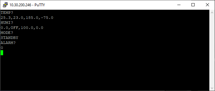
The following flowchart shows how to set target temperature to 50°C, target humidity to 80%, and the constant mode. Refer to Section 3.3 for details on how to apply the setting commands.

The following depicts the series of commands issued to the chamber from the host computer (running a software such as PuTTY).
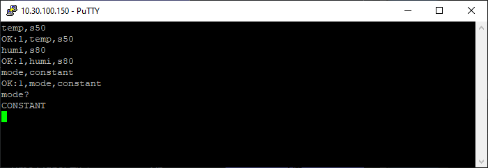
Note: The last command "MODE?" is not part of the flowchart; it was issued to confirm the operating status. It could be added to the flowchart above the End block as input box with: Send "MODE?" to chamber
The following presents an example to create a program that specifies the initial condition(s) on temperature and/or humidity SP or PV. The program also contains a step (or statement) that executes a new program when the current program completes all its steps. As an example, the next program to be executed is program number 15. This program must exist before the current program is executed. This program example also illustrates the use of GL looping feature.
To start programming from remote communication, it's a good idea to issue "PRGM USE?" command first to determine the next available program slot.
PRGM USE?
In the response, the first number specifies the total number of programs, followed by program numbers, listed in sequence, separated by commas. This information allows us to determine the next program number to use. Note: If any program number in sequence is skipped or missing, that slot is available for creating (or storing) a new program.
Procedure:
-
Proceed to establish communication via TCP or Serial.
-
Probe the number of program(s) and program slots already in use:
PRGM USE? -
Determine and decide the program number to use for the new program.
-
Enter the following steps sequentially:
PRGM DATA WRITE,PGM25,EDIT STARTPRGM DATA WRITE,PGM25,PRE MODE, TEMP, SVPRGM DATA WRITE,PGM25,PRE TSV,25.5PRGM DATA WRITE,PGM25,STEP1,TEMP26.8,GOTEMP30.0,TIME1:00PRGM DATA WRITE,PGM25,STEP2,TEMP35,TRAMP OFF,GRANTY ON, REF0, TIME1:00PRGM DATA WRITE,PGM25,STEP3,TEMP35,GOTEMP45.0,TIME1:00PRGM DATA WRITE,PGM25,COUNT,A(2.3.4),B(0.0.0)PRGM DATA WRITE,PGM25,STEP4,TEMP45,GOTEMP OFF,GRANTY ON,TIME1:00PRGM DATA WRITE,PGM25,END,RUN,PTN15,STEP1PRGM DATA WRITE,PGM25,NAME,PROGNAME, where "PROGNAME" is the name of the program being created.PRGM DATA WRITE,PGM25,EDIT END -
Reissue the "PRGM USE?" command to check if the program has been created successfully.
-
To execute the program remotely, issue:
PRGM RUN,RAM:25,STEP1
GP-IB communication protocol is currently unsupported. However, this section outlines the details of the GP-IB communication protocol for future operation when it becomes available. Cable and signal lines must conform to IEEE standard.
Table 5.1 Pin Assignment
| Pin No. | Signal | Connection |
|---|---|---|
| 1 | DI01 | Connected |
| 2 | DI02 | Connected |
| 3 | DI03 | Connected |
| 4 | DI04 | Connected |
| 5 | EO1 | Connected |
| 6 | DAV | Connected |
| 7 | NRFD | Connected |
| 8 | NDAC | Connected |
| 9 | IFC | Connected |
| 10 | SRQ | Connected |
| 11 | ATN | Connected |
| 12 | Shield | Connected |
| 13 | DI05 | Connected |
| 14 | DI06 | Connected |
| 15 | DI07 | Connected |
| 16 | DI08 | Connected |
| 17 | REN | Connected |
| 18 | DAV ground | Connected |
| 19 | NRFD ground | Connected |
| 20 | NDAC ground | Connected |
| 21 | IFC ground | Connected |
| 22 | SRQ ground | Connected |
| 23 | ATN ground | Connected |
| 24 | EO1 and REN ground | Connected |
Address: Address can be selected from 1 ~ 16 and changed from the instrumentation panel. It is not necessary to restart the system after changing the address.
Interface Support
| Function | Level | Remarks |
|---|---|---|
| Source handshake | SH1 | Contains all source handshake capabilities. |
| Acceptor handshake | AH1 | Contains all acceptor handshake capabilities. |
| Talker | T6 | Basic talker; Serial port; Does not have talk only MLA talker cancel. |
| Listener | L4 | Basic listener; Does not have listen only MTA listener cancel. |
| Service request | SR1 | Service request |
| Remote-Local | RL2 | Contains all remote-local functions except local lockout. However, does not support GTL address command. |
| Parallel poll | PP0 | Does not have parallel poll. |
| Device clear | DC1 | Contains all device clear functions. |
| Device trigger | DT0 | Does not have device trigger. |
| Controller | C0 | Does not have system controller; Does not have IFC send/controller-in-charge; Does not have REN send; Does not have SRQ response; Does not have interface message; Does not have control receive; Does not have control relinquish; Does not have self control receive/relinquish; Does not have parallel poll; Does not have control receive/relinquish in synch with handshake. |
Control Bus Support
Table 5.3 Control Bus Support
| Control Bus | Support | Remarks |
|---|---|---|
| ATN | Supported | Confirms to IEEE488 |
| IFC | Supported | Confirms to IEEE488 |
| REN | Supported | Confirms to IEEE488 |
| SRQ | Supported | Confirms to IEEE488 Note: Supports serial poll but not parallel poll. |
| EO1 | Supported | Confirms to IEEE488 |
Universal Command Support
Table 5.4 Universal Command Support
| Command | Support | Remarks |
|---|---|---|
| LLO | Not Supported | To make communication control unconditional when communications are enabled. |
| DCL | Supported | Operates the same as in IFC reception. |
| PPU | Not Supported | Does not have a parallel poll, so PPU support is unnecessary. |
| SPE | Supported | Support SRQ, therefore SPE support is necessary. |
| SPD | Supported | Support SRQ, therefore SPD support is necessary. |
Address Command Support
Table 5.5 Address Command Support
| Command | Support | Remarks |
|---|---|---|
| GTL | Not Supported | |
| SDC | Supported | Confirms to IEEE-488. |
| PPC | Not Supported | Does not have a parallel poll, so PPC support is unnecessary. |
| GET | Not Supported | To make communication control unconditional when communications are enabled. |
| TCT | Not Supported | Does not have controller capabilities. |
Figure 5.1 Serial Poll Register
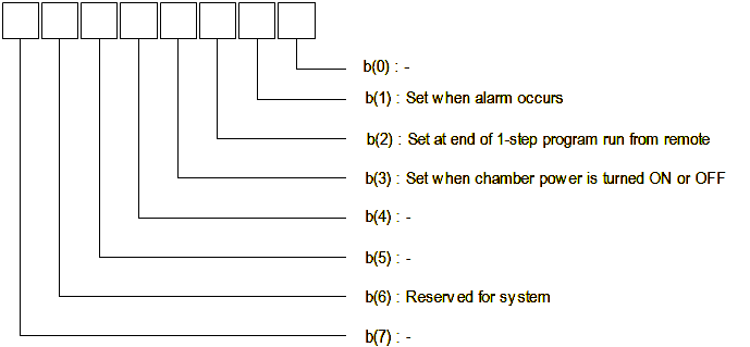
The serial cable for data transmission and communication must meet the specified requirement of the EIA RS-232C Standard, an equivalent to the Japanese Industrial Standard or RS-232C JIS C-6361.
The serial communcation is between the embedded computer that hosts the GL controller system and the PC that runs the software to host the communication protocol. A null-modem cable is required for this connection. Connection can also be established using a straight-through cable bridged with a null-modem adaptor.
To ensure the correct pin connection, examine the pin assignment in the following table.
Table 5.6 RS-232C Pin Assignment
| Pin No. | Signal (JIS) | Signal | Connection |
|---|---|---|---|
| 1 | FG | Protective ground or cable shield | Not Connected |
| 2 | SD | Transmission data | Connected |
| 3 | RD | Reception data | Connected |
| 4 | DR | Data set ready | Connected |
| 5 | SG | Signal line ground | Connected |
| 6 | ER | Data terminal ready | Connected |
| 7 | CS | Transmission enabled | Connected |
| 8 | RS | Send request | Connected |
The RS-232C communication system is based on an asynchronous, unipolar (or bipolar), full-duplex, serial communication standard. The communication system is setup with data sent in packets with bits framed together to form a complete message. To synchronize data framing, it applies start bits, data bits, parity bits (for error checking) and stop bits to end the message. Its full-duplex feature utilizes separate Tx and Rx lines to allow simultaneous communication.
The following table outlines the characteristics of the RS-232C communication process.
| Type | Description |
|---|---|
| Communication System | Modulated full-duplexing |
| Transmission Rate | Selectable from 4800, 9600 and 19200 bps (see figure below). Can be selected from the instrumentation panel. It is not necessary to restart the system after changing the transmission rate. |
| Data Bit | Data length: 8 Stop bits: 1 Parity check: OFF The above setting cannot be changed by users. |
| Flow Control | Xon/Xoff control: OFF Si/So control: OFF The above setting cannot be changed by users. |
| Local Echo | Not supported |
The following figure depicts the RS-232C configuration provided by the GL controller system.
Table 5.7 RS-485 Pin Assignment
| Pin No. | Signal (JIS) | Signal | Connection |
|---|---|---|---|
| 1 | SD+ | Send Data + | Connected |
| 2 | SD- | Send Data - | Connected |
| 3 | RD+ | Receive Data + | Connected |
| 4 | RD- | Receive Data - | Connected |
| 5 | GND | Signal Ground | Connected |
| 6 | GND | Signal Ground | Connected |
The following table outlines the characteristics of the RS-485 communication process.
| Type | Description |
|---|---|
| Communication System | Bi-directional full duplex. |
| Transmission Rate | Selectable from 4800, 9600 and 19200 bps. Can be selected from the instrumentation panel. It is not necessary to restart the system after changing the transmission rate. |
| Maximum Transmission Distance | 500M |
| Maximum Number of Chambers Connectable | 16 |
There are several choices available for communications software.
For remote communication via Ethernet TCP/IP protocol, an SSH and Telnet terminal emulator, called PuTTY, can be used. It is a free implementation of SSH and Telnet for MS Windows and GNU/Linux or UNIX platforms, which can be downloaded at this web site:
https://www.chiark.greenend.org.uk/~sgtatham/putty/
Please refer to the legal warning posted on the web site.
Refer to Section 2.1.5 for a step-by-step procedure to set up PuTTY on your MS Windows-based PC.
For remote communication via serial interface (e.g., RS-232C), Termite RS232 terminal (by CompuPhase) can be used to communicate and control the GL controller. It is a free software for personal and commercial use.
https://www.compuphase.com/software_termite.htm
The following figure depicts a typical serial configuration to connect to the GL controller for remote control and operation.
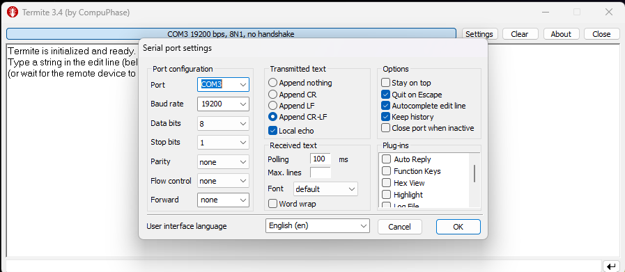
Users who need to program their own solution may look into LabVIEW drivers using an RS-232C interface. For more information, visit ESPCE support web page at:
https://espec.com/na/products/controllers/gl_controller
Additionally, independent programming solutions to control the GL controller are available via the application of ChamberConnectLibrary using Python 3. The library is available as an AS-IS software at GitHub. The user simply downloads or clones the library from GitHub (available to the public), build or create Python 3 environment to use the library.