The RIOT fork in this organization is watched by a bot (@powerprofiler). Whenever a pull request is made, the bot will measure the power consumption of each of the applications in this repository on the codebase in the pull request.
The process for each application is as follows:
- The pull request is downloaded to the power baselining server
- A Hamilton mote is powered on
- JTAG probes are physically connected to the device
- The application is compiled and flashed
- The JTAG probes are completely disconnected (by means of relays) to prevent leakage current on the debug pins
- The board is subjected to a sequence of 'trials'. Each trial run consists of
- Power cycle the device and allow it a few seconds to settle
- Make an educated guess as to the average current draw
- Switch to providing EXACTLY that current, no more, no less
- If the parallel-attached ideal capacitor bank charges up too much, the guess was too high, if it discharges too much, the guess was too low. "Too much" is by default 200 mV, so the device is powered with 3.2V nominal and the trip thresholds are at 3.0V and 3.4V
- Make a better guess and repeat
For resilience against time-correlated effects such as ambient temperature changes, only the initial sequence of guesses are made following a binary search. Once a bracket on the 'correct' value is estimated, the program switches to evaluating a shuffled list of currents within the bracket. Each current within the bracket is trialed 5 times, generally leading to hundreds of trials in total.
If a trial lasts a certain amount of time without tripping on either threshold (60 seconds by default), then we need a new mechanism for deciding which trial is "more accurate". As the system was designed to profile duty cycling devices, we cannot simply use the voltage on the capacitor and the end of the trial - this is more about luck and where in a given duty cycle you happen to measure. If you measure straight after the active part, the cap will be very low. If you measure just before it, the cap will be high. Instead, we continuously measure the voltage across the cap throughout the trial and compute the sum of the squares of the difference between the measured voltage and the start voltage (3.2V). An accurate guess's trial will oscillate around 3.2V, as the current flowing from the calibrated current source exactly matches the average current of the device. It will therefore have a lower sum of squares than an inaccurate guess that will slowly drift either higher or lower.
While this system only provides a single number: the average current, it does so very accurately. There is no error introduced by an uncalibrated shunt resistor (this combined with an oscilloscope is the most common way of obtaining current traces). We are not dependent on the value of the capacitor, only that it remains constant and has no leakage. Often, researchers will attempt to use an ammeter or a source meter to measure a device and quickly realize that it only works for steady-state. For a duty-cycling device, you not only struggle with range problems (20mA active vs 20uA idle) but your sample rate is quite low (often 120Hz or lower) meaning that you will miss the short spikes in current typical of waking up to send a radio packet or sample a sensor. The setup we use is as accurate as the current source, and the leakage of the cap. In our case that's accurate to 50 pA on the source and probably 10nA on the caps, although I think the variation in the MCU will exceed that.
At the end of the trials, the @profilebot will comment on the pull request and give you the results. Generally just the number is enough, but sometimes you may want to look at the deviation graph yourself to estimate the error in the answer.
In order for this jig to work, the application must have periodic behavior. For example, if you want to test how power efficient your radio duty cycling code is, then you must have an application that wakes up and sends a packet every second for example, and continues to do so ad infinitum. The applications must not require any stdin to work: the device under test does not have a UART nor debug probes attached, as those interfere with accurate power consumption results.
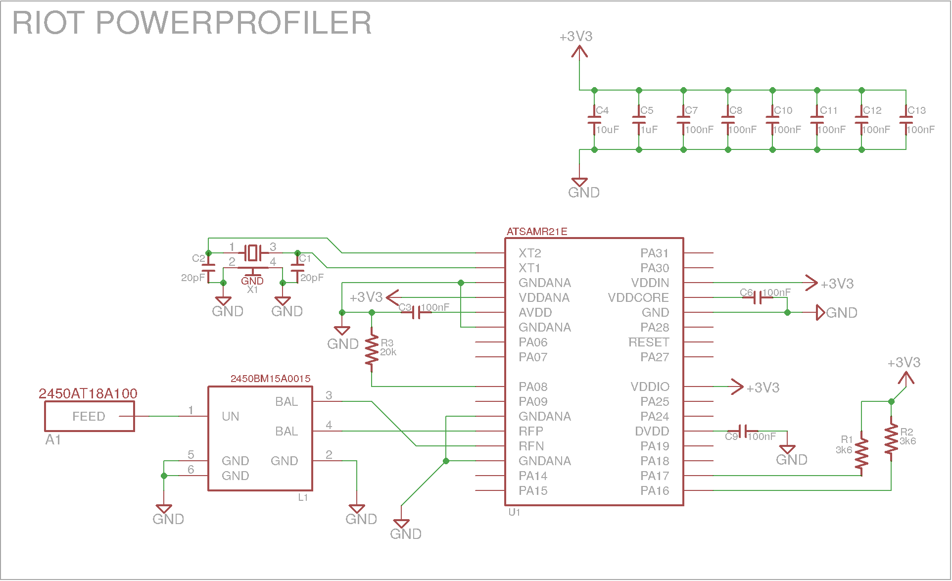
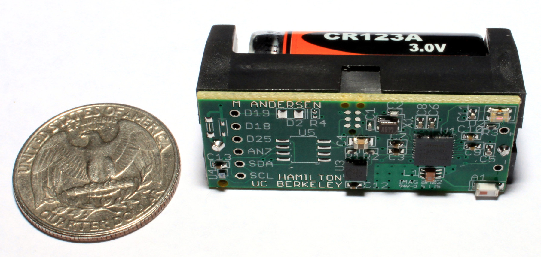 The Hamilton mote (so named for its $10 cost) is a board based on the ATSAMR21E18A (similar to the MCU present on the SAMR21XPRO). Normally, the Hamilton also has an accelerometer, temperature sensor and light sensor but for the power measurement rig, these have been removed so that they do not interfere with power consumption. The schematic for the modified boards looks as follows:
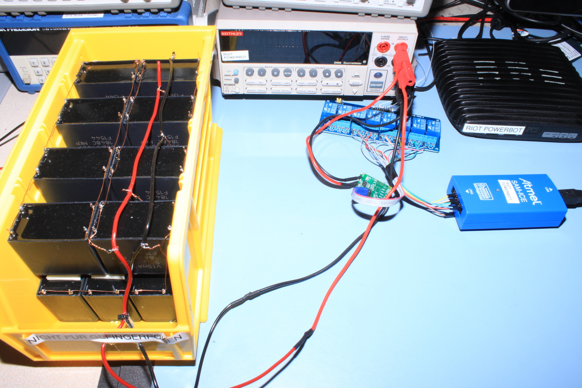
The full test rig looks like this:
If there are any problems with the power profiler, please create an issue on PowerProfiler/RIOT.