This GitHub repository describes about the 1 -Bit, 4-Bit Logic Unit (ALU) using Circuit Verse.
- ALU stands for Arithmetic Logic Unit.
- It is a combinational digital circuit that performs arithmetic and bitwise operations.
- Gated circuits control The flow of bits and the operations performed on them in the ALU subunits.
- It’s an important component of a computer’s Central Processing Unit (CPU).
- In this Project, performs Addition, Subtraction, NAND, and NOR operations.

- It can perform any simple arithmetic operations (add, sub, etc..) and logical operations such (And, OR) etc.
- Depending on the ‘OP’ selected, the result is to be shown at the ‘OUT’.
- It stands as an Integrated Circuit (IC) (74181). It also can be synthesized using VHDL.
A Basic ALU supports these common logic operations. Arithmatic Operation:-
- ALU accepts the inputs in binary format and performs the Add (with carry), Sub (with Borrow), Two's complement etc.
- The inputs are summed, subtracted or performed the required operations and show up the output in the "OUT."
- in the two's complement, an input is subtracted from the zero and the output appears in "OUT."
- AND- the bitwise operation of AND appears in the "OUT."
- And so on. it can show up to any logic function such as, OR, XOR, XNOR, NAND, NOR etc.
- It supports parallel architecture and applications with high performance.
- It has the capability of performing instructions on a very large set and has a high range of accuracy.
In the above attached image the ALU is 1 Bit and only can perform Full Addition, Full Subtraction, NAND and NOR operation.
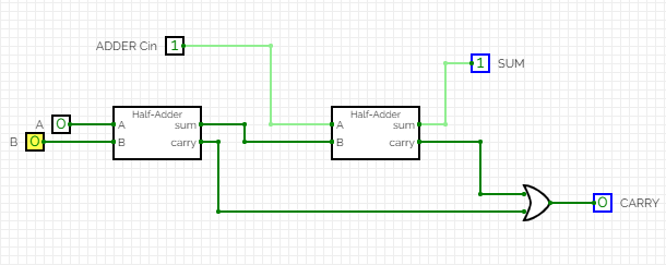
- A full Adder is a Combinational Circuit which can take 3 inputs at a time and show the addition result.
- The addition results are labelled as SUM and CARRY.
- A full adder is a cascade connection of 2 half adders.
- An extra input is then provided to the half adder-2 and both the carry from the half-adders are performed OR operation to get the CARRY for the Full-Adder.
- Here the full-adder is created using the sub-circuit of the half adder.
- sub-circuit are the self contained circuits that appears as black boxes.
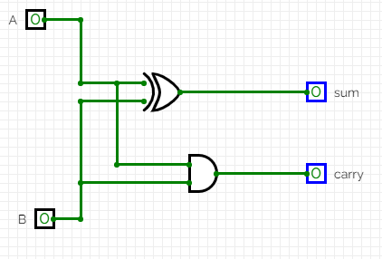
- A half adder can take only 2 inputs and perform the operation.
- While the sum is taken out by the XOR operation of the both the inputs, the CARRY is taken out by the AND operation of the both inputs.
- The expression for the SUM is SUM = (A ^ B). CARRY= (A & B).
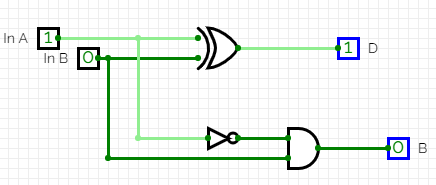
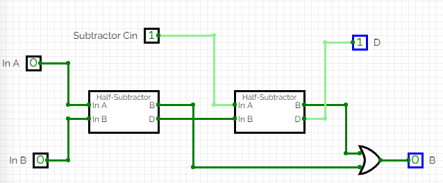
- The half subtractor has the same structure as the half adder has.
- Only change is that, it has a NOT gate placed at the any one input at the carry section.
- But, in subtractor, we call the sum as the "Difference" or "D" and the carry is known as "Borrow" or "B."
- The expression for the DIFFEENCE is DIFFERENCE = (A ^ B). BORROW= (A' & B).
- The connection of the full subtractor is as same as a full adder, i.e, placing two half-subtractors in cascade.
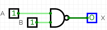
- NAND gate is also known as Universal Gate, as we can implement any circuit using this gate itself.
- This is just a combination of AND and followed by a NOT gate.
- In the ALU, the Sub-Circuit of the NAND gate is being used.
- The expression for the NAND gate is X= ~(A & B).
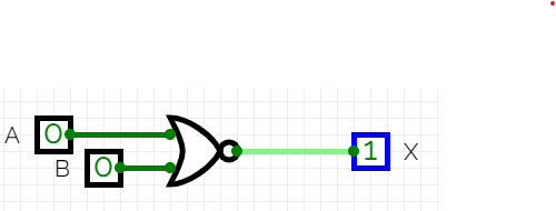
- Like NAND, NOR is also known as a Universal gate.
- This is just a combination of OR and followed by a NOT gate.
- In the ALU, the Sub-Circuit of the NOR gate is being used.
- The expression for the NOR gate is X= ~(A | B).