Repository navigation
Electronics Forum #2

Replies: 0 comments 70 replies

|
So I went the hard way and got the components together to build the DSPIRA LNA (I actually built two). I found the cover shield was ridiculously expensive in small quantities but solved this by milling a small aluminium case for the LNA that internally approximately matches the dimensions of the shield. Testing so far shows that these LNAs are working but I have yet to put them on an antenna. Regards |

|
Hi David
It is absolutely great that you’ve got two working amplifiers that you’ve built!
There is a way of testing the performance without an horn antenna
that you should try first.
This requires only a very inexpensive termination, available from Amazon.
(Two for $6 or 5 for $10)
See: http://wvurail.org/lightwork/memos/LightWorkMemo028-r7-NoiseTemp.pdf
You should be getting an effective temperature of between 80 to 100 Kelvins.
Your telescope will work with an effective temperature under 300 Kelvins.
Best regards
Glen
https://www.amazon.com/YOTENKO-coaxial-Terminator-Termination-Connector/dp/B07TQ5J5C2/ref=sr_1_4?crid=2JQHA2A6NDD4O&dchild=1&keywords=50+ohm+terminator+sma&qid=1632421417&sprefix=50+ohm+ter%2Caps%2C152&sr=8-4
… On Sep 23, 2021, at 1:24 AM, ZL4DK ***@***.***> wrote:
So I went the hard way and got the components together to build the DSPIRA LNA (I actually built two). I found the cover shield was ridiculously expensive in small quantities but solved this by milling a small aluminium case for the LNA that internally approximately matches the dimensions of the shield. Testing so far shows that these LNAs are working but I have yet to put them on an antenna.
I am using a HackRF One clone as the receiver. This seems to be working OK also. I must admit I am struggling with Linux. My old laptop seems to be overflowing with the data coming in from the HackRF (strings of zeros printed in the bottom left window) but that doesn't seem to be stopping the software.
I have a SDRPlay receiver also, but haven't managed to get this working with GNUradio.
Regards
David
—
You are receiving this because you are subscribed to this thread.
Reply to this email directly, view it on GitHub, or unsubscribe.
Triage notifications on the go with GitHub Mobile for iOS or Android.
|
|
Thanks Glen, |

|
Hi Dave,
Glad you’re making progress.
Hopefully Pranav or Kevin will update the parts list value for that resister. I’m wondering
if the amplifiers ordered recently have that part error!
I’m not sure which spectrometer you mean by GNUradio spectrometer.
However that will probably work, but you need to average for about a minute on the “hot” and “cold”
measurements (code is just no load attached), so you’ll need to figure out how to do averaging.
The NsfIntegrate programs do that and also do the “Y” factor to compute the effective
noise temperature. (This is a simple calculation, but is a little unusual).
(See online documents like: https://www.osti.gov/servlets/purl/1562649)
Concerning the raspberry PI, a 4B with 4 GBytes of memory is plenty.
The newer, PI 400, is actually slightly better, but does not fit
in the box I use. I’ve got one running at a horn, but just in a plastic
bag, not a sturdier, weather tight box. So far it has not gotten
soaked with rain, after about 6 months outside.
Good Luck!
Glen
The code for the Pi is all completely on-line and in one single, very big (3.3 GByte),
download. The same code works for both the Pi 4B and Pi 400.
… On Sep 23, 2021, at 4:05 PM, ZL4DK ***@***.***> wrote:
This email originated from outside of the National Science Foundation. Do not click links or open attachments unless you recognize the sender and know the content is safe.
Thanks Glen,
yes I did try this last night. Initially I had no success and on investigating I found almost no voltage across the SAV-541. I found I had a 27k Ohm resistor in R2 instead of 27 Ohm. I had been following https://github.com/WVURAIL/dspira/blob/master/labs/06/2018_06_22.pdf and this error is in the parts list (the schematic is correct).
I changed this resistor for a 30 ohm one (I didn't have a 27 Ohm) and it seems to be good now, although I haven't done the full test to work out the effective temperature yet.
I'm running the GNUradio spectrometer software on a laptop rather than the NSFintergrate on a RPi. I assume they are roughly the same thing.
I might look at getting a RPi they seem pretty good. Is there a recommended RAM size?
—
You are receiving this because you are subscribed to this thread.
Reply to this email directly, view it on GitHub, or unsubscribe.
Triage notifications on the go with GitHub Mobile for iOS or Android.
|

|
Hi @ZL4DK, good spotting the error in the parts list. you were referring to an outdated document on a outdated website that we have since updated to reflect new and corrected stuff. you might want to refer to this: a distro image for raspberry pi and a general document is also here https://wvurail.org//dspira-lessons/RaspberryPi if you want to add more to this as you experiment do let me know |
|
OK so if a have understood correctly Y = Hot_Output/Cold_Output |
|
And just to try it again I reduced the gain on my HackRF One receiver and now have a Hot signal of 130 and a cold signal of 19. this gives a Temperature of 51K. |
|
Hi Dave,
Well that is a great number for the Rx Effective temperature.
Kevin Bandura’s design has given me the best measure Tsys on
an antenna that I’ve gotten.
I’ve not directly measured the T_rx_ on my copy of his
amplifier, as it has been so reliable that I’ve always
had it on a telescope. (Currently 5 are running).
So, I’d say that 51K is lower than I’ve measured, but is
still physically possible. I actually use T hot = 290K
and T cold = 10K, for my measurements, but there is not too
much justification for my T cold.
It would be great if you’d write up your measurements as
a LightWork Memo. It seems like you’ve done a careful job.
Maybe add a couple pictures and repeat your measurements 3
times to see if the gain is change with time. That’s the only
effect that I’m aware of that might be an issue. That
is, I’ve found that for some amplifiers the gain decreases
as they warm up, so doing hot first, then cold second shows
a lower T_rx_. But if you Cycle through 3 measurements you
can see any trends.
Thanks for your measurements!
Glen
… On Sep 23, 2021, at 8:17 PM, ZL4DK ***@***.***> wrote:
And just to try it again I reduced the gain on my HackRF One receiver and now have a Hot signal of 130 and a cold signal of 19. this gives a Temperature of 51K.
—
You are receiving this because you commented.
Reply to this email directly, view it on GitHub, or unsubscribe.
Triage notifications on the go with GitHub Mobile for iOS or Android.
|
|
I tested my second LNA and this isn't so good. Cold gave a reading of 52 and hot a reading of 160 which equates to a temperature of 140K. Yes I repeated the readings a few times cycling between hot and cold and there is a slight drift as things warm up but not excessive. |
|
Hi ZL4DK (aka Dave?),
Well, you’ve made great progress! Actually having lower than 150K LNA effective temp is
better than most commercial amplifier boards will give.
Glad to hear the amplifier gain is not changing too much during your tests.
Since galactic hydrogen is really remarkably bright, peak > 50 K, both your amplifiers will
enable you to easily see our galaxy.
So is your 50K amplifier measurement repeatable? That is a great number! The GBT has
amplifiers, cryogenically cooled, that have an effective temp of 19 Kelvins.
As I said I’ve got 5 horns, with different combinations of amplifiers. I have a range of
Tsys values from 140 to 240 K, by hot-cold measurements. This includes a foam insulation top
of all the horns, to keep them from collecting too many leaves and too much snow and rain.
The “lid” seems to add about 25 Kelvin. The horns have been outside for several years now.
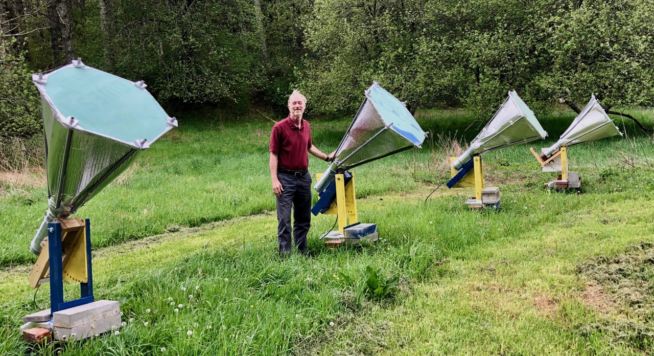
(See: https://www.gb.nrao.edu/~glangsto/Glen+4Horns.jpg)
The hot-cold load test actually measures the ratio of Tsys/(gain efficiency), so a
higher reading likely indicates the gain is a little low.
(ie not all the signal is making it to the first LNA).
A parabolic antenna with feed probe at focus has a gain efficiency between 0.5 and 0.7.
Horns can be more efficient, gain = 0.8 to 0.95, but are difficult to make very large.
My larger horns are about 32 inches in diameter, which is about 80cm.
It would be great if someone would write up measurements of hot-cold temperature
using the WVURAIL horn design.
My horns are all cylinders, and I got a professional to calculate the optimum
feed probe position and length, to improve gain.
Congratulations on your success!
Glen
PS I’m working on a memo showing how to measure the properties of our galaxy:
1) our speed of rotation
2) number of arms
3) mass of the disk near the Sun
… On Sep 24, 2021, at 6:47 AM, ZL4DK ***@***.***> wrote:
I tested my second LNA and this isn't so good. Cold gave a reading of 52 and hot a reading of 160 which equates to a temperature of 140K. Yes I repeated the readings a few times cycling between hot and cold and there is a slight drift as things warm up but not excessive.
I set up my antenna (a 1200mm dish) and can easily see the Hydrogen bump with either LNA.
After calibrating (hot point at Ground and cold pointing at cold sky) the system temperature chart showed a line at 160K for the good LNA and 300K for the not so good one. However some of that might be my antenna. The mount I have only allows me to swing it a limited amount and I had trouble pointing it completely at the ground and trouble pointing it completely away from any hydrogen when cold. It probably has a few bad sidelobes also.
—
You are receiving this because you commented.
Reply to this email directly, view it on GitHub, or unsubscribe.
Triage notifications on the go with GitHub Mobile for iOS or Android.
|
|
HI ZL4DK,
I confirm your calculations. According to the references
(eg https://www.osti.gov/servlets/purl/1562649, equations 59, 60 and 61),
Y = N_hot/N_cold
where The Ns are measurements, in counts, from your SDR.
Then the Receiver temperature is
T_rx = (T_hot - (Y * T_cold))/(Y - 1)
So for your case
Y = 130/19 = 6.8
You (and I) assume T_hot = 290K and you assume T_cold = 0K, then
T_rx = (290K - (6.8 * 0K))/5.8 = 50 K, which is about what you reported.
Now let’s consider the error estimate for the measurements
The uncertainty appears to be +/- 1 in for both measurements.
The cold measurement dominates, so
Y’ = 130/(19 +/- 1) = 6.5 to 7.2, then estimate the Y uncertainty as 0.7/2 => 6.8+/-0.35
So T_rx could be between 47K and 53K, so a fairly tight range.
Now I use Tcold = 10K (not zero)
This tweaks the results to
T_rx = (290 - (6.8 *10))/5.8 = 38 K. Which is even lower. So maybe your number is better.
So, I confirm your calculations.
Best regards
Glen
… On Sep 23, 2021, at 8:17 PM, ZL4DK ***@***.***> wrote:
And just to try it again I reduced the gain on my HackRF One receiver and now have a Hot signal of 130 and a cold signal of 19. this gives a Temperature of 51K.
—
You are receiving this because you commented.
Reply to this email directly, view it on GitHub, or unsubscribe.
Triage notifications on the go with GitHub Mobile for iOS or Android.
|
|
OK this is cool. The sky is full of interesting signals. At noon today while pointing straight up I got a very large single peak. I think this is from the direction of the Southern Cross. (I'm at 170.386 E and 45.889 S) Time zone is currently UTC +13. Earlier this morning I got a smaller but more interesting double humped red shifted signal from I think the direction of Vela. Regards |
|
OK Just for news I have an update on my LNA construction and testing efforts. I had purchased 3 circuit boards so finally got the components together and got the third one going. Initially this looked faulty and I finally found a bit of solder shorting the top of R16 to ground. Clearing this fixed the problem and the LNA performed as good as the first one with a noise temp of actually slightly less than 50K. Regards |
|
Dear David,
That’s fantastic news. Would you mind writing up a very short
LightWork Memo on that topic? It would be very valuable to others
to hear of your good success both making ant testing Kevin’s amplifier.
They would appreciate some documentation of your measurements.
(https://github.com/WVURAIL/lightwork)
Everyone should really do the noise measurement test before starting their
observations, as it provides an easy, and pretty accurate, check that the
whole system is working.
Best regards
Glen
Glen I Langston, Ph. D.
Galactic Astronomy Program Director
National Science Foundation
304-456-3032
… On Oct 9, 2021, at 8:07 PM, ZL4DK ***@***.***> wrote:
This email originated from outside of the National Science Foundation. Do not click links or open attachments unless you recognize the sender and know the content is safe.
OK Just for news I have an update on my LNA construction and testing efforts. I had purchased 3 circuit boards so finally got the components together and got the third one going. Initially this looked faulty and I finally found a bit of solder shorting the top of R16 to ground. Clearing this fixed the problem and the LNA performed as good as the first one with a noise temp of actually slightly less than 50K.
This made me look harder at the second one that didn't seem to be doing as well as it should.
I decided to try changing the SAV-541 thinking maybe I had a poor performing one. In the process of removing it I got a blob of solder on C2 and when removing this C2 fell off the board revealing that I hadn't soldered it properly on one side. I figured this was probably the source of my problem. I re-soldered C2 and installed the new SAV-541 (I figured I'd close to cooked the old one by now) and now have a third LNA working with a noise temp of 50K so am very happy. I plan to keep two of the LNAs but will look for a local school or other worthy recipient for the third. Thanks again for the help.
Regards
David
—
You are receiving this because you commented.
Reply to this email directly, view it on GitHub, or unsubscribe.
Triage notifications on the go with GitHub Mobile for iOS or Android.
|
|
Hi DSPIRA and all Aficionados,
Hope everyone is doing well.
I’m working on providing example “experiments" and data for folks wanting
to do some radio astronomy on their own.
Jupyter notebooks are the currently fashionable way of mixing programming
and executing of example programs. There’s a huge amount of online documentation.
The code is starting to come together. Get a version by typing (on a linix/mac system):
cd ~
git clone https://github.com/glangsto/jupyter <https://github.com/glangsto/jupyter>
cd jupyter
jupyter-lab
Then you’re in and can run the programs.
(You may need to install jupyter-lab)
(See https://jupyterlab.readthedocs.io/en/stable/getting_started/installation.html <https://jupyterlab.readthedocs.io/en/stable/getting_started/installation.html>)
The lesson goals are:
1) Have a few simple goals for people to try with Horn Radio Telescope Data already available
2) Make it possible to use either the NSF series of Gnuradio programs or
spectrometer_w_cal.grc to use the software tools.
i) I’ve started conversion programs, toCsv to convert the NSF .ast and .hot files
to the type of files that are compatible with spreadsheets
see: https://github.com/glangsto/jupyter/blob/master/ConvertObsToCsv.ipynb <https://github.com/glangsto/jupyter/blob/master/ConvertObsToCsv.ipynb>
3) Have a basic understanding of the Milky Way structure.
See: https://github.com/glangsto/jupyter/blob/master/MilkyWay1Intensity.ipynb <https://github.com/glangsto/jupyter/blob/master/MilkyWay1Intensity.ipynb>
You might start with this notebook as it models the Milky Way without data.
4) To Be done: Compare observations to the Model
Please give these a try and let me know what you think.
Thanks!
Glen
FYI I’m having a good bit of trouble getting spectrometer_w_cal.grc to write files.
We might want to have the “prefix” displayed in the interface and allow it to be changed.
For a beginners guide to Jupyter notebooks look at
https://www.dataquest.io/blog/jupyter-notebook-tutorial/ <https://www.dataquest.io/blog/jupyter-notebook-tutorial/>
… On Sep 17, 2021, at 11:32 AM, Joe Wise ***@***.*** ***@***.***>> wrote:
Awesome. We are looking forward to getting some data from your site.
We were able to get two telescopes to serve as an interferometer last summer.
If you are interested, I can send you information. Further work will be required. It is a tricky proposition.
Joe Wise
|
|
Hi Kenric,
First of all you have made great progress!
That you have 7 horns means you have a whole observatory!
You can definitely use the RTL-SDRs and see the Milky Way. But you MUST
change the center frequency to 1,420.5MHz (or about), because you are
missing Galactic Hydrogen.
Note, it will be very hard to see the Milky Way, before calibration.
Also you need more gain, as the counts should range between +/- .1 counts.
Right now you are seeing either interference or features in the SDR.
Set the SDR gain to max, which is around 50, I think.
You are close to success!
Make these changes and let us know how it goes.
Glen
…On Sun, Feb 26, 2023 at 3:25 PM kenric-davies ***@***.***> wrote:
Hi Everyone,
Let preface by saying that I am a complete novice on most of the details
of the operation of this project(Linux, radio telescopes, etc.) but I am
always willing to learn so that I can provide experiences for my students.
I am having some issues that I'm hoping the group can help with. My high
school astronomy students have built 7 of these horn telescopes and I am in
the process of learning how to use the GNUradio program and trying to get
them operational. The program is running and I am seeing the graph on the
screen but it does not seem like I am actually receiving data from the
telescope.
I am working off a Nooelec LNA (https://www.nooelec.com/store/lana.html)
and I have a 3 AA (4.5 V) battery pack providing power (the power LED is
lit). I also have an RTL-SDR (
https://www.amazon.com/RTL-SDR-Blog-RTL2832U-Software-Defined/dp/B0129EBDS2/ref=sr_1_3?crid=F24JV9EGEG41&keywords=RTL-SDR&qid=1660857000&sprefix=%2Caps%2C471&sr=8-3)
plugged into the computer.
I have made the noted adjustments in the program to have the RTL-SDR
instead of the Airspy but I am just not seeing any sort of change in the on
screen graph while trying to operate the horn.
If it helps, here are some links to screenshots/data:
Here is a screenshot of the program while running -
https://drive.google.com/file/d/18olujRV0EKNldoUlaUyYd8MJZGiKUuty/view?usp=share_link
Here is the graph that was "printed" from the program -
https://drive.google.com/file/d/1hSQKqxj9u_ooJuLFYjuCKo7hhA5OXw6c/view?usp=share_link
I noticed that the on screen graph is not centered on 1420 MHz which I
find odd considering the goal of the program. The "heartbeat" in the top
right of the screen is changing but is not at the same peak height as I
have seen in some of the DSPIRA videos.
I would appreciate any help that any of you can offer me or things that I
can check to help troubleshoot.
Thanks!
Kenric Davies
—
Reply to this email directly, view it on GitHub
<https://github.com/WVURAIL/dspira-lessons/issues/8#issuecomment-1445458734>,
or unsubscribe
<https://github.com/notifications/unsubscribe-auth/AALEY7GRBO3SKIVDO63A4XTWZO35FANCNFSM5ES3FZEQ>
.
You are receiving this because you commented.Message ID:
***@***.***>
|
|
Hi again,
It is good to power the LNA by battery pack, but in that case make sure the
RTL bias is off. Your screen shot shows there is too little signal getting
to the SDR, so either the 1st LNA is not working or you need to set the SDR
gain higher.
Again, great work!
Glen
…On Sun, Feb 26, 2023 at 3:25 PM kenric-davies ***@***.***> wrote:
Hi Everyone,
Let preface by saying that I am a complete novice on most of the details
of the operation of this project(Linux, radio telescopes, etc.) but I am
always willing to learn so that I can provide experiences for my students.
I am having some issues that I'm hoping the group can help with. My high
school astronomy students have built 7 of these horn telescopes and I am in
the process of learning how to use the GNUradio program and trying to get
them operational. The program is running and I am seeing the graph on the
screen but it does not seem like I am actually receiving data from the
telescope.
I am working off a Nooelec LNA (https://www.nooelec.com/store/lana.html)
and I have a 3 AA (4.5 V) battery pack providing power (the power LED is
lit). I also have an RTL-SDR (
https://www.amazon.com/RTL-SDR-Blog-RTL2832U-Software-Defined/dp/B0129EBDS2/ref=sr_1_3?crid=F24JV9EGEG41&keywords=RTL-SDR&qid=1660857000&sprefix=%2Caps%2C471&sr=8-3)
plugged into the computer.
I have made the noted adjustments in the program to have the RTL-SDR
instead of the Airspy but I am just not seeing any sort of change in the on
screen graph while trying to operate the horn.
If it helps, here are some links to screenshots/data:
Here is a screenshot of the program while running -
https://drive.google.com/file/d/18olujRV0EKNldoUlaUyYd8MJZGiKUuty/view?usp=share_link
Here is the graph that was "printed" from the program -
https://drive.google.com/file/d/1hSQKqxj9u_ooJuLFYjuCKo7hhA5OXw6c/view?usp=share_link
I noticed that the on screen graph is not centered on 1420 MHz which I
find odd considering the goal of the program. The "heartbeat" in the top
right of the screen is changing but is not at the same peak height as I
have seen in some of the DSPIRA videos.
I would appreciate any help that any of you can offer me or things that I
can check to help troubleshoot.
Thanks!
Kenric Davies
—
Reply to this email directly, view it on GitHub
<https://github.com/WVURAIL/dspira-lessons/issues/8#issuecomment-1445458734>,
or unsubscribe
<https://github.com/notifications/unsubscribe-auth/AALEY7GRBO3SKIVDO63A4XTWZO35FANCNFSM5ES3FZEQ>
.
You are receiving this because you commented.Message ID:
***@***.***>
|

|
Hi Glen, Thank you for the information, I was able to get the 1420 MHz in the center of the graph so I am at least one step closer! I adjusted the RF Gain to 50 (from 17) and that seemed to help the signal strength on the graph but I'm not sure what I am seeing (screenshots linked below). I am still thinking that I am not actually passing a signal to the computer and here is why. I mentioned that I am using a battery pack to power the LNA connected to the horn and this one has an LED showing when it is receiving power. When I have the battery pack connected, the LED is turned in showing power. When I connect the input side to the horn, the LED is still lit; but, when I connect the cable that runs to the SDR, the LED goes off! This makes me think that the LNA is not actually on and passing a signal to the computer. Another reason I think I am not actually seeing anything is that nothing will change on the program graph output when I am moving it around the sky or even pointing at the ground! Here are more screenshots to help you all see what I am doing wrong... screenshot of the Gnuradio program flow (upper half) - https://drive.google.com/file/d/17BiHWTEJUNPpRiBXIGjRGwFhVY2EQZgY/view?usp=share_link screenshot of program while running - https://drive.google.com/file/d/1gEqABn765-w8TNxX8wkZCvUyVKxAh_52/view?usp=share_link graph output - https://drive.google.com/file/d/1bDn9tj0r-EuJ9GYPjN3FwwVcuItjuZln/view?usp=share_link I have tried following the video and doing the calibration but I am just not seeing any change on the graph so I can't find a place with "no Hydrogen" bump to do the Cold Calibration step. Any help you can give would be much appreciated! Kenric |
|
Hi Kenric,
It seems like there is a problem with the power to the LNA when you have the SDR connected.
Note that the RTLSDRs have plenty of power to drive the amplifier, so that no additional battery pack is connected.
There is a software step to turn the RTLSDR power on and off.
Please take a look at LightWork memo 28
https://github.com/WVURAIL/lightwork/blob/master/memos/LightWorkMemo028-r7-NoiseTemp.pdf
Which has an example using the RTLSDR, showing the bandpass shape. Look at page 8 in the memo.
Probably you need to set the “BIAS-TEE” OFF if using your battery pack, but without the battery pack,
and the BIAS-TEE ON, the light should be on on the LNA you have. Then you should see a band pass shape like
is shown in the memo. Note that both the software I use and spectrometer_w_cal should give similar results.
For my tests, I used a program that we wrote called NsfIntegrate24.grc (and .py)
that sets the RTLSDR for 2.4 MHz, which I’d also recommend. It appears you’re using 2.0 MHz.
The linux commands for the bias T are
rtl_biast -b 1
To turn the bias tee on
and
rtl_biast -b 0
to turn it off.
These commands are probably already installed in your system if you’re getting any data at all.
Glen
Summary:
Try turning the bias tee on with these commands, while disconnecting your batter pack.
If the light goes on on the amplifier, you are good to go.
… On Feb 28, 2023, at 7:14 PM, kenric-davies ***@***.***> wrote:
Hi Glen, Thank you for the information, I was able to get the 1420 MHz in the center of the graph so I am at least one step closer! I adjusted the RF Gain to 50 (from 17) and that seemed to help the signal strength on the graph but I'm not sure what I am seeing (screenshots linked below).
I am still thinking that I am not actually passing a signal to the computer and here is why. I mentioned that I am using a battery pack to power the LNA connected to the horn and this one has an LED showing when it is receiving power. When I have the battery pack connected, the LED is turned in showing power. When I connect the input side to the horn, the LED is still lit; but, when I connect the cable that runs to the SDR, the LED goes off! This makes me think that the LNA is not actually on and passing a signal to the computer.
Another reason I think I am not actually seeing anything is that nothing will change on the program graph output when I am moving it around the sky or even pointing at the ground!
Here are more screenshots to help you all see what I am doing wrong...
screenshot of the Gnuradio program flow (upper half) - https://drive.google.com/file/d/17BiHWTEJUNPpRiBXIGjRGwFhVY2EQZgY/view?usp=share_link
screenshot of program while running - https://drive.google.com/file/d/1gEqABn765-w8TNxX8wkZCvUyVKxAh_52/view?usp=share_link
graph output - https://drive.google.com/file/d/1bDn9tj0r-EuJ9GYPjN3FwwVcuItjuZln/view?usp=share_link
I have tried following the video and doing the calibration but I am just not seeing any change on the graph so I can't find a place with "no Hydrogen" bump to do the Cold Calibration step.
Any help you can give would be much appreciated!
Kenric
—
Reply to this email directly, view it on GitHub, or unsubscribe.
You are receiving this because you commented.Message ID: ***@***.***>
|
|
Hello again Kenric,
I now see that you have the bandwidth set at 2.4MHz which is good.
My main guess is that the RTLSDR is shorted with the battery pack.
Fortunately it has a good current limiting circuit. so probably
no damage is done to the RTL or amplifier.
My guess is also you need to change the Osmocom block to have input to
rtlsdr=0,bias=1
And remove the battery pack.
See what your signal looks like. Make sure the amplifier light is on.
I just tested building spectrometer_w_cal.grc and these changes built fine,
but i could not test them.
Glen
***@***.*** ***@***.***>
Note I use VNC for all my telescopes and have a raspberry pi computer at each
of the 4 of them. This allows login from anywhere in the world.
… On Feb 28, 2023, at 10:48 PM, Glen Langston ***@***.***> wrote:
Hi Kenric,
It seems like there is a problem with the power to the LNA when you have the SDR connected.
Note that the RTLSDRs have plenty of power to drive the amplifier, so that no additional battery pack is connected.
There is a software step to turn the RTLSDR power on and off.
Please take a look at LightWork memo 28
https://github.com/WVURAIL/lightwork/blob/master/memos/LightWorkMemo028-r7-NoiseTemp.pdf
Which has an example using the RTLSDR, showing the bandpass shape. Look at page 8 in the memo.
Probably you need to set the “BIAS-TEE” OFF if using your battery pack, but without the battery pack,
and the BIAS-TEE ON, the light should be on on the LNA you have. Then you should see a band pass shape like
is shown in the memo. Note that both the software I use and spectrometer_w_cal should give similar results.
For my tests, I used a program that we wrote called NsfIntegrate24.grc (and .py)
that sets the RTLSDR for 2.4 MHz, which I’d also recommend. It appears you’re using 2.0 MHz.
The linux commands for the bias T are
rtl_biast -b 1
To turn the bias tee on
and
rtl_biast -b 0
to turn it off.
These commands are probably already installed in your system if you’re getting any data at all.
Glen
Summary:
Try turning the bias tee on with these commands, while disconnecting your batter pack.
If the light goes on on the amplifier, you are good to go.
> On Feb 28, 2023, at 7:14 PM, kenric-davies ***@***.***> wrote:
>
>
> Hi Glen, Thank you for the information, I was able to get the 1420 MHz in the center of the graph so I am at least one step closer! I adjusted the RF Gain to 50 (from 17) and that seemed to help the signal strength on the graph but I'm not sure what I am seeing (screenshots linked below).
> I am still thinking that I am not actually passing a signal to the computer and here is why. I mentioned that I am using a battery pack to power the LNA connected to the horn and this one has an LED showing when it is receiving power. When I have the battery pack connected, the LED is turned in showing power. When I connect the input side to the horn, the LED is still lit; but, when I connect the cable that runs to the SDR, the LED goes off! This makes me think that the LNA is not actually on and passing a signal to the computer.
> Another reason I think I am not actually seeing anything is that nothing will change on the program graph output when I am moving it around the sky or even pointing at the ground!
> Here are more screenshots to help you all see what I am doing wrong...
> screenshot of the Gnuradio program flow (upper half) - https://drive.google.com/file/d/17BiHWTEJUNPpRiBXIGjRGwFhVY2EQZgY/view?usp=share_link
> screenshot of program while running - https://drive.google.com/file/d/1gEqABn765-w8TNxX8wkZCvUyVKxAh_52/view?usp=share_link
> graph output - https://drive.google.com/file/d/1bDn9tj0r-EuJ9GYPjN3FwwVcuItjuZln/view?usp=share_link
> I have tried following the video and doing the calibration but I am just not seeing any change on the graph so I can't find a place with "no Hydrogen" bump to do the Cold Calibration step.
> Any help you can give would be much appreciated!
> Kenric
> —
> Reply to this email directly, view it on GitHub, or unsubscribe.
> You are receiving this because you commented.Message ID: ***@***.***>
|
|
Hi Glen, I am still not getting the light on the amplifier to turn on. I have tried using the linux command before starting Gnuradio with the battery pack off and get the following message: Found 1 device(s): Using Device 0: Generic RTL 2832U OEM But the light on the amplifier is still off. I started Gnuradio and made the adjustments there but still no light and the signal again like I'm not getting anything. I feel like yesterday, when I was trying it, I was able to get the light to stay (with battery pack) on when plugging the SDR into one specific port on my laptop but today cannot reproduce this. The light (if battery pack connected) immediately goes out if SDR is connected. Am I wrong in thinking that the Input side of the amplifier should be connected to the Horn and the output connected to the SDR? If I hook it up the other way, the light stays on but no change in signal. Thanks for all of the troubleshooting. Kenric Any other ideas? |
|
Hi Kenric,
Glad you’re keeping at this. But I’m now puzzled.
Are there any filters between the amplifier and the SDR?
A high pass filter will block the DC voltage from reaching the Amplifier.
Also look for any shorts in your RF cabling.
The messages (below) look good.
What command did you use to get these messages?
Did you use:
rtl_test
or
rtl_biast
?
Please try the following.
Completely turn off python spectrometer_w_cal.grc (or.py)
Connect the amplifier to the RTLSDR (via coaxial cable).
Note there may also be an issue with the coaxial cable.
What type of cable (and how long) are you using.
ON the Linux command line run:
rtl_test
then, run
rtl_biast -b 1
See if the light goes on and also capture all messages,
including the commands you used to get the messages.
Please send us your results.
We continue to hope you have good luck with this!
Best regards
Glen
glen.i.langston -at at at- gmail.com
From: kenric-davies ***@***.***>
Sent: Thursday, March 2, 2023 10:41 AM
To: WVURAIL/dspira-lessons ***@***.***>
Cc: Langston, Glen ***@***.***>; Comment ***@***.***>
Subject: [EXTERNAL] - Re: [WVURAIL/dspira-lessons] dspira-lessons/forum/electronics/ (#8)
This email originated from outside of the National Science Foundation. Do not click links or open attachments unless you recognize the sender and know the content is safe.
Hi Glen,
I am still not getting the light on the amplifier to turn on. I have tried using the linux command before starting Gnuradio with the battery pack off and get the following message:
Found 1 device(s):
0: Realtek, RTL2838UHIDIR, SN:00000001
Using Device 0: Generic RTL 2832U OEM
Found Rafael Micro R828D tuner
But the light on the amplifier is still off.
I started Gnuradio and made the adjustments there but still no light and the signal again like I'm not getting anything.
I feel like yesterday, when I was trying it, I was able to get the light to stay (with battery pack) on when plugging the SDR into one specific port on my laptop but today cannot reproduce this. The light (if battery pack connected) immediately goes out if SDR is connected.
Am I wrong in thinking that the Input side of the amplifier should be connected to the Horn and the output connected to the SDR? If I hook it up the other way, the light stays on but no change in signal.
Thanks for all of the troubleshooting.
Kenric
Any other ideas?
—
Reply to this email directly, view it on GitHub<https://github.com/WVURAIL/dspira-lessons/issues/8#issuecomment-1452076223>, or unsubscribe<https://github.com/notifications/unsubscribe-auth/AADRXGGQ3XFXU4TEI3TJVKLW2C5PNANCNFSM5ES3FZEQ>.
You are receiving this because you commented.Message ID: ***@***.******@***.***>>
|
|
I used the rtl_biast command. I will try your suggestions when I get a chance and let you know the outcome. In the meantime, I'll let you know something that I just found that might be the issue. I have been googling around to see what might be going on with the biast command since you indicated that I "should" have the commands installed with Linux and came across something strange. Apparently the RTL-SDRs have been counterfeited and being sold from other sources with the reviews saying many things around the bias t not working like it should. Looking at mine against the ones shown on the RTLSDR.com website and I believe, when my school ordered these, I have the counterfeit ones because they apparently did not use the specific link to amazon that I gave them (which would be just me luck!). I will be ordering one myself from the link provided on the source website to see if maybe that is it before trying to get my school district to send the 7 we purchased back and reorder new ones (which will be an uttur pain!). Thanks again for all of the help and I'll keep you posted! Kenric |
|
Hi Kenric,
Another thought on what might be going on with your telescopes.
I think the “clone” RTL-SDRs still work, but I’m not sure about the bias-tee.
When you battery-power the amplifier, I think the voltage is also on the
coaxial line back to the RTL-SDR. The SDR may act as a short, stopping
the battery pack from powering the amplifier.
In this case you may need a high-pass filter between the amplifier and the RTLSDR.
There are some specifically for Neutral hydrogen, which will also reduce your sensitivity
to interference.
I’ve not yet tried this filter, available on Amazon, but it is $26.00 and could
greatly help your project. To find it, go to amazon.com <http://amazon.com/> and search for:
"RF Filter Module 1420MHz BPF Band Pass Power Distribution Control Electronic"
If you put this between your SDR and the amplifier, the light on the amplifier
should stay on when you use your battery pack.
Glen
I just ordered the filter to try it out. It will arrive in a week.
I’ll let you know if it is any good.
… On Mar 2, 2023, at 12:03 PM, kenric-davies ***@***.***> wrote:
I used the rtl_biast command.
I will try your suggestions when I get a chance and let you know the outcome. In the meantime, I'll let you know something that I just found that might be the issue. I have been googling around to see what might be going on with the biast command since you indicated that I "should" have the commands installed with Linux and came across something strange. Apparently the RTL-SDRs have been counterfeited and being sold from other sources with the reviews saying many things around the bias t not working like it should. Looking at mine against the ones shown on the RTLSDR.com website and I believe, when my school ordered these, I have the counterfeit ones because they apparently did not use the specific link to amazon that I gave them (which would be just me luck!).
I will be ordering one myself from the link provided on the source website to see if maybe that is it before trying to get my school district to send the 7 we purchased back and reorder new ones (which will be an uttur pain!).
Thanks again for all of the help and I'll keep you posted!
Kenric
—
Reply to this email directly, view it on GitHub, or unsubscribe.
You are receiving this because you commented.Message ID: ***@***.***>
|
|
Hi Glen, Looking back at the reviews of the SDR that was actually purchased, it seems like the bias-tee is non-functional on these cloned versions. I received an authentic RTL-SDR today (thank you Amazon Prime) and the bias-tee has worked. The light on the LNA stays lit while connected to the SDR and without the battery pack. I now have a different graph on the screen but have some similar issues. Here is what the screen looks like now - https://drive.google.com/file/d/1iogD_1enPfiFbrxYBPTWWT6xkVNBkPpl/view?usp=share_link I tried going through the calibration process detailed in one of the YouTube videos and, again, no matter where I point in the sky, the graph stays the same. This has me thinking that the construction of the horn is incorrect in some manner. Reviewing the instructions for assembling the horn, I believe that the antenna is in the wrong place. My students put it on the short side of the can instead of the middle of the long side. The copper wire is still the same length detailed in the instructions (5.5 cm I think). Thank you so much for the help so far and I am grateful if you have any other thoughts about what might be happening. Kenric |
|
HI Kenric and all,
Thanks for the pictures you sent. I think these explain a good bit.
Your DISPRA Spectrometer spectrum does show a reasonable spectrum
for the SDR. The RTL-SDRs always have three broad peaks which
are due to the SDR electronics, not due to the sky.
These features are completely removed by calibration.
However your students will need to move the “feed probe” to the wide
side of the can. That will probably allow detection of the Milky Way.
You will need to calibrate to see the Milky Way, which will be a peak
in the spectrum at about 1420.4 MHz.
Also note that you will need to make a “Long integration” both for calibration
and for your observation of the Milky Way.
Note that the Milky Way signal varies by a factor of about 50, depending on where/when you
are looking at the sky.
In the Galactic Plane the signal will be up to 50 Kelvins (calibrated) and down to
about 1 or 2 Kelvins when you are looking at Milky Way South or North Pole.
Note that over most of the Northern Hemisphere you can see both north and south
galactic poles, because the Earth (and solar system) are oriented sideways to the rotation
of the Milky Way.
The single level about +/-0.1 counts (in the System Heartbeat plot is about right,
but could be just a little stronger maybe as much as +/- 0.2 counts. The signal might
increase when your students move the feed probe.
So, you’re getting there. Good Luck,
Keep us posted on your progress,
Best regards
Glen
PS Where are you? I’m in West Virginia, right next to the Green Bank Observatory.
From: kenric-davies ***@***.***>
Sent: Saturday, March 4, 2023 7:02 PM
To: WVURAIL/dspira-lessons ***@***.***>
Cc: Langston, Glen ***@***.***>; Comment ***@***.***>
Subject: [EXTERNAL] - Re: [WVURAIL/dspira-lessons] dspira-lessons/forum/electronics/ (#8)
This email originated from outside of the National Science Foundation. Do not click links or open attachments unless you recognize the sender and know the content is safe.
Hi Glen,
Looking back at the reviews of the SDR that was actually purchased, it seems like the bias-tee is non-functional on these cloned versions. I received an authentic RTL-SDR today (thank you Amazon Prime) and the bias-tee has worked. The light on the LNA stays lit while connected to the SDR and without the battery pack. I now have a different graph on the screen but have some similar issues.
Here is what the screen looks like now - https://drive.google.com/file/d/1iogD_1enPfiFbrxYBPTWWT6xkVNBkPpl/view?usp=share_link
I tried going through the calibration process detailed in one of the YouTube videos and, again, no matter where I point in the sky, the graph stays the same. This has me thinking that the construction of the horn is incorrect in some manner. Reviewing the instructions for assembling the horn, I believe that the antenna is in the wrong place. My students put it on the short side of the can instead of the middle of the long side. The copper wire is still the same length detailed in the instructions (5.5 cm I think).
Here is a picture - https://drive.google.com/file/d/1Nq9xednT9Mg3LxMZlgk1mQklPlKJN6d_/view?usp=share_link
Thank you so much for the help so far and I am grateful if you have any other thoughts about what might be happening.
Kenric
—
Reply to this email directly, view it on GitHub<https://github.com/WVURAIL/dspira-lessons/issues/8#issuecomment-1454928847>, or unsubscribe<https://github.com/notifications/unsubscribe-auth/AADRXGGAN2OL7ZWKZA4F3PLW2PJXZANCNFSM5ES3FZEQ>.
You are receiving this because you commented.Message ID: ***@***.******@***.***>>
|
|
I think that I have had a successful test! I hope :) I brought a horn home to do more testing and I had the means to move the antenna. I just took it out and the graph did change as I moved the horn around the sky so I was able to successfully go through the calibration process. Here are the results: Screenshot of program - https://drive.google.com/file/d/1gjiFOkjEndto3Rw4mMVlb6sWx1FC5chL/view?usp=share_link Graph print to file - https://drive.google.com/file/d/1XkodF1_qxEaTKY3A6pC-mD2dhRFqEsLZ/view?usp=share_link The data is rough even on long integration probably because I was in my front yard with trees and such around so not a real good clear sky (if that matters). I was pointed in the general direction of Cygnus (around 270-290 azi and below 45 alt at 6:00 pm from Frisco, TX). I think I am seeing a bump in the graph at 1420.31 indicating galactic hydrogen with a doppler shift showing around -20 km/s of speed. I would love if anyone would have a chance to check to see if these readings are valid. Glen - to officially answer your questions, I am in Frisco, TX (north Dallas area). Thank you for the help in getting this project moving forward! I appreciate the community here and the willingness to help the novice. Kenric P.S. - I have been using the lessons on measuring the speed of the Earth around the Sun and I have been pretty impressed. Thank you to all of you who have been a part of that process. |
|
Hi Kenric,
Congratulations!
Yes, your seeing parts of the Milky Way moving at great velocity.
As you observe, the peak of the doppler velocity will change.
Great work,
Glen
… On Mar 5, 2023, at 7:19 PM, kenric-davies ***@***.***> wrote:
I think that I have had a successful test! I hope :)
I brought a horn home to do more testing and I had the means to move the antenna. I just took it out and the graph did change as I moved the horn around the sky so I was able to successfully go through the calibration process. Here are the results:
Screenshot of program - https://drive.google.com/file/d/1gjiFOkjEndto3Rw4mMVlb6sWx1FC5chL/view?usp=share_link
Graph print to file - https://drive.google.com/file/d/1XkodF1_qxEaTKY3A6pC-mD2dhRFqEsLZ/view?usp=share_link
The data is rough even on long integration probably because I was in my front yard with trees and such around so not a real good clear sky (if that matters). I was pointed in the general direction of Cygnus (around 270-290 azi and below 45 alt at 6:00 pm from Frisco, TX). I think I am seeing a bump in the graph at 1420.31 indicating galactic hydrogen with a doppler shift showing around -20 km/s of speed. I would love if anyone would have a chance to check to see if these readings are valid.
Glen - to officially answer your questions, I am in Frisco, TX (north Dallas area).
Thank you for the help in getting this project moving forward! I appreciate the community here and the willingness to help the novice.
Kenric
P.S. - I have been using the lessons on measuring the speed of the Earth around the Sun and I have been pretty impressed. Thank you to all of you who have been a part of that process.
—
Reply to this email directly, view it on GitHub, or unsubscribe.
You are receiving this because you commented.Message ID: ***@***.***>
|


Uh oh!
There was an error while loading. Please reload this page.
Uh oh!
There was an error while loading. Please reload this page.
Discuss telescope electronics and receiver hardware.
All reactions