The main focus of this project is to run a Home Assistant application to be able to keep track of all of the devices within the garage that have been created so far (see Labs 1-4). Home Assistant can be run on many different platforms such as Docker containers, Raspberry pi’s, and on top of other OS systems and can integrate different forms of communication from within the platform. It is not only an easy method for communicating between devices, but allows the user to see the status of all devices on one platform.
- Use three Arduino Wemos D1 Mini’s
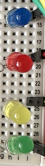
- Use a breadboard, LEDs (red, green, yellow, blue), and resistors to create one of the circuits
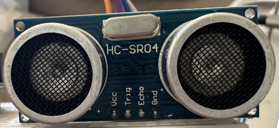
- Use a breadboard and a distance sensor to create the second circuit
- Use a breadboard and a magnetic sensor to create the third circuit
- Run home assistant on any available platform
- Connect the arduino’s to home assistant
- When the distance sensor senses something very close, the red light flashes
- When the distance sensor senses something close, the red light turns on
- When the distance sensor senses something at a medium distance, the yellow light turns on
- When the distance sensor senses something at a larger distance, the green light turns on
- When the distance sensor senses anything within that larger distance, the blue LED illuminates
- When the distance to sensor exceeds a large reasonable distance, any illuminated LED or current blink mode is stopped and the machine is in the off state
- Reasonable time interval for each flash in the blink mode is used
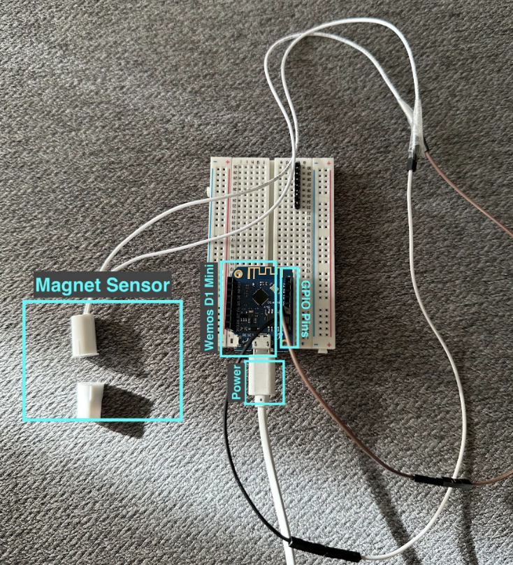
The user facing interface for this system is a physical stoplight (Figure 1) that is visible to the user, a distance sensor (Figure 2), and a magnet sensor (Figure 3), and the Home Assistant UI (Figure 4) to interact with. The user will be able to move an object at varying distances from the sensor and be able to witness different colours of lights that will indicate how far away that object is. The user will also be able to connect and disconnect the magnet sensor to turn the light system on and off. This is representative of a garage parking distance sensor. As the user moves into the garage, the light will change based on distance sensor readings and the status of the garage door (magnet sensor). A distant user will also be able to witness the status of all of the devices through the Home Assistant UI, allowing them to keep an eye on their garage.

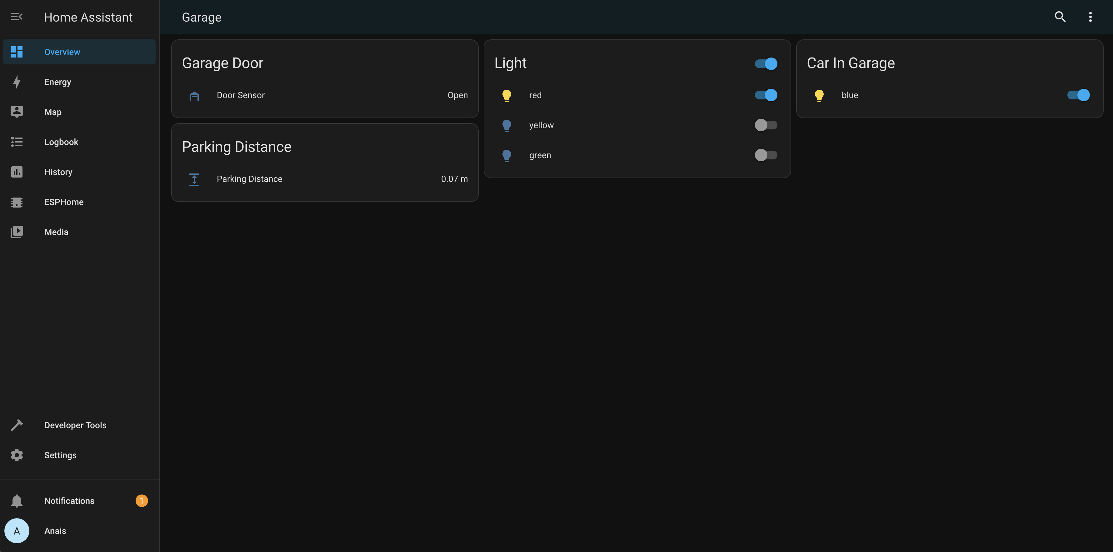
The User Interface on Home Assistant allows the user to see the exact distance an object is away from the sensor, whether or not the garage door is opened or closed, the status of the light used for parking and each individual LED on it, and to see whether the car is in the garage. The system is set to change based on events from these entities, but the distant user has access to change certain components from this interface.
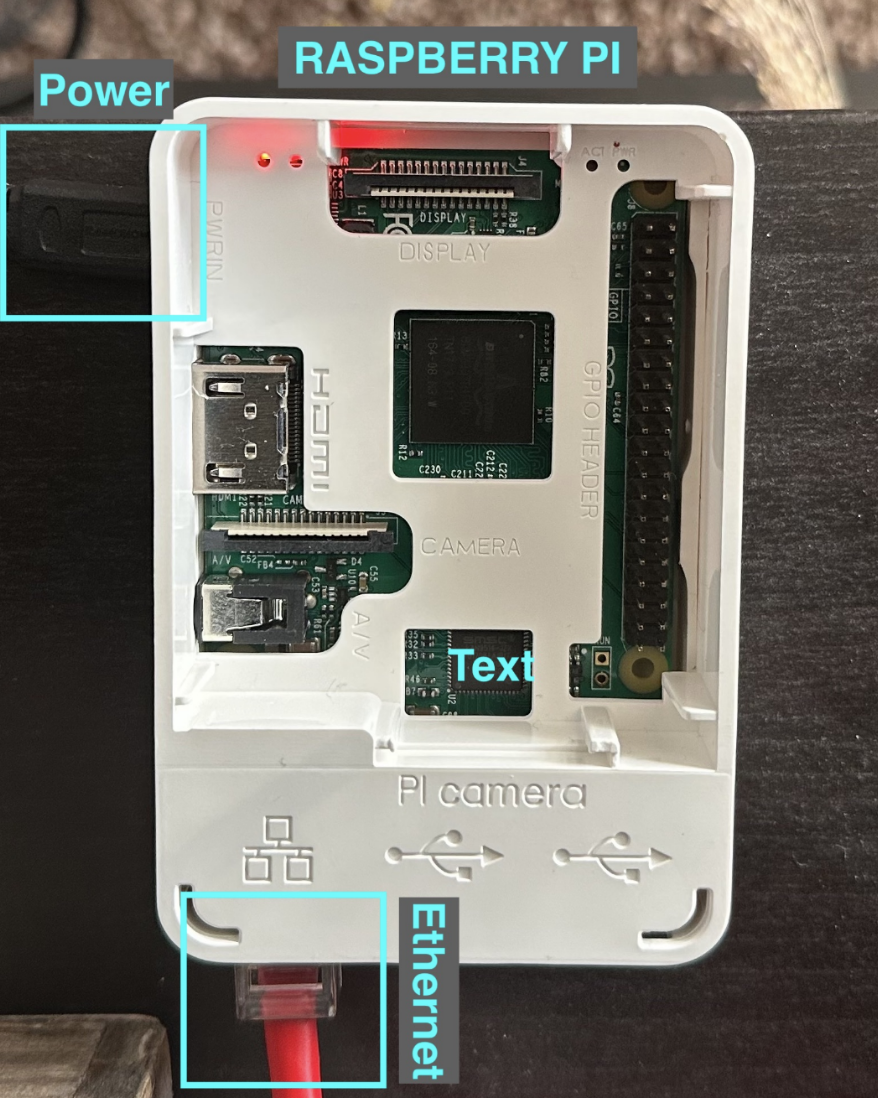
There are four main components for this lab. There is the raspberry pi, the stop light, the distance sensor, and the magnet sensor.
For the raspberry pi (figure 5), a few changes had to be made to the pi. The Micro SD card was removed and the software belenaEtcher was used to flash the Home Assistant software onto the pi. After waiting for the system to boot up, the system is ready to go on http://homeassistant.local:8123 on your computer connected to the same network. This webpage is what is used to hook up devices, configure the functionality of all the devices, and add rules dependent on the state each device is in. The main dashboard is customizable to be able to suit the user’s needs.
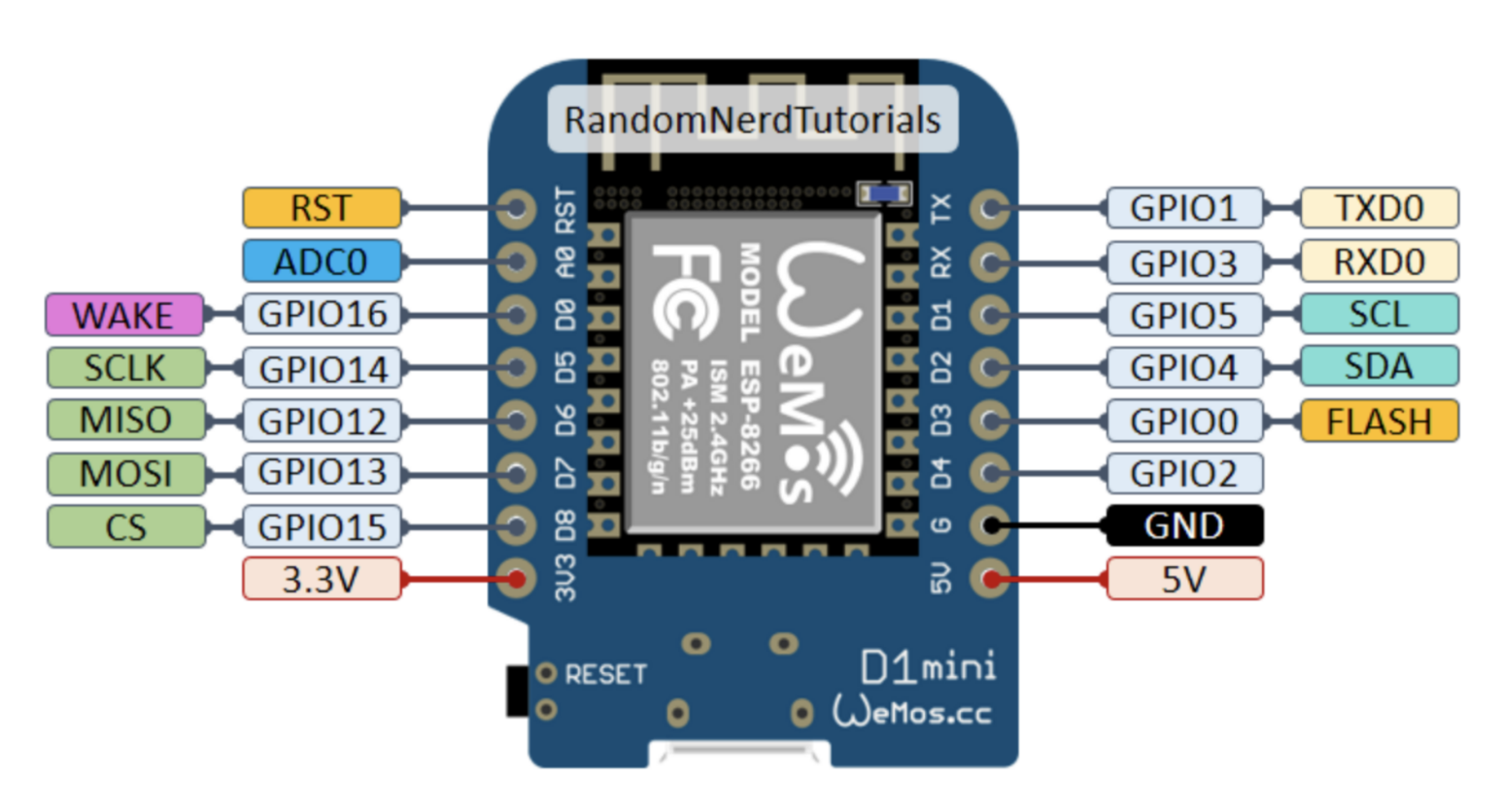
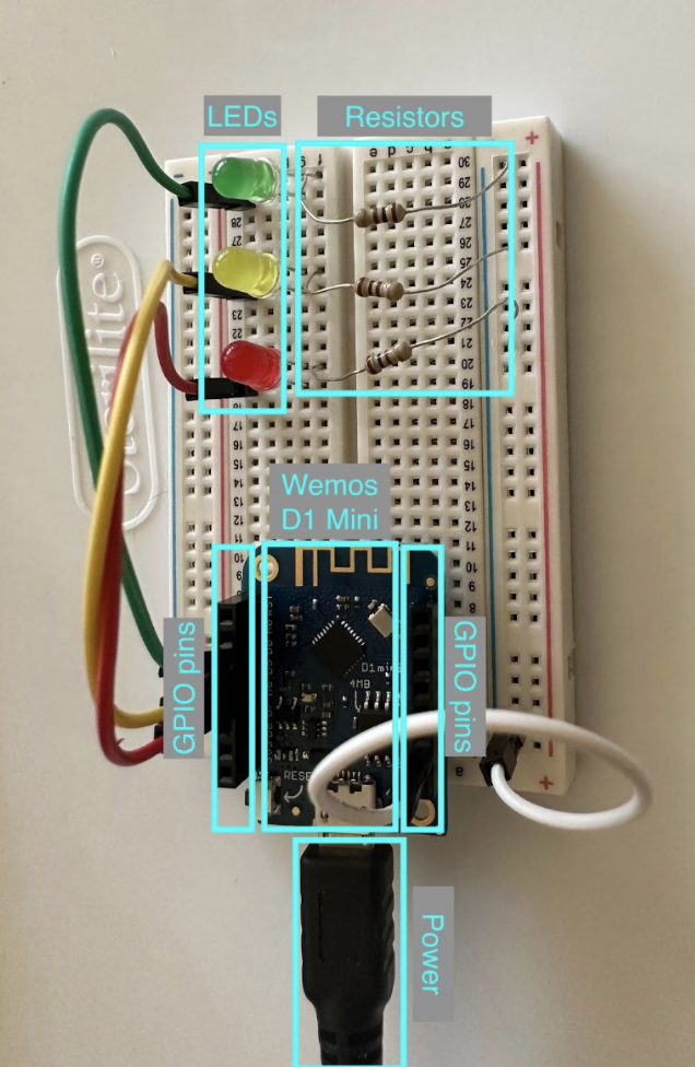
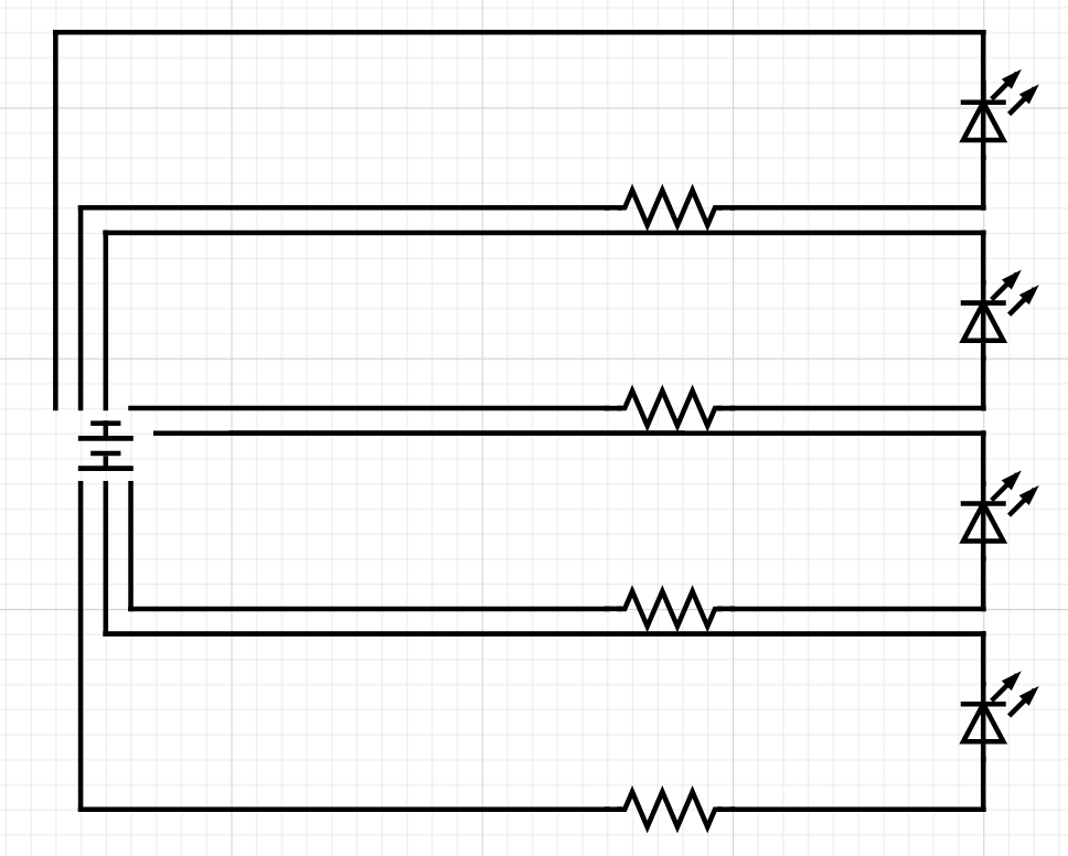
The circuit for the stoplight has a few parts. The main driver of the whole system is the Wemos arduino D1 mini. This is programmed through a yaml file that is installed on the arduino. This yaml file is generated through the Home Assistant user interface and edited to read the sensor before sending to the arduino. The yaml can be installed through various methods, but the method used for this lab was by connecting the arduino to the raspberry pi, and selecting the method to install using a wired connection to a platform hosting the Home Assistant software. There are also some LED lights (red, yellow, and green) that indicate the different distances from the sensor. The red LED is connected to pin D6, the yellow LED is connected to pin D5, and the green is connected to pin D0. There is a blue LED as well that indicates whether there is a vehicle in the garage. There are also resistors that are provided so that the LEDs do not blow from too much voltage. These are connected to the ground wire, connected to the ground pin. Lastly, we have the power source which is connected to the arduino through a micro usb cable.
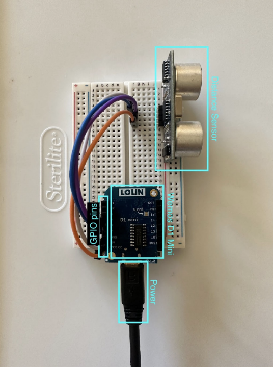
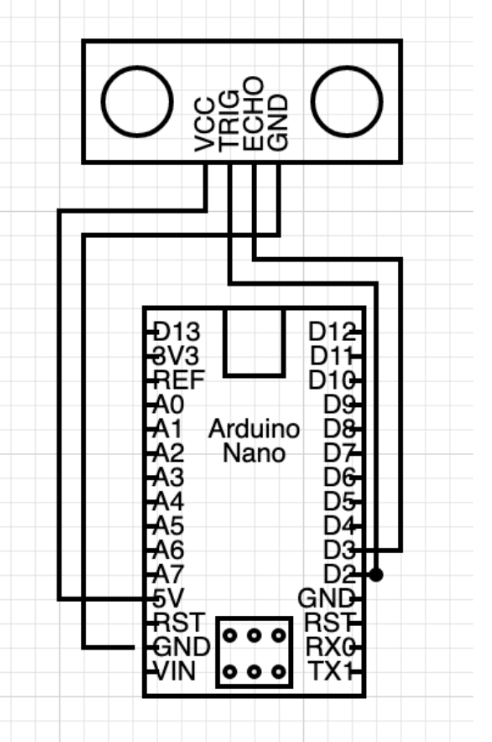
The circuit for the sensor also has a few parts. Like the stoplight, a Wemos arduino D1 mini is also programmed using a yaml file (see appendix). The other part of this circuit is the sensor (HC-SR04) itself. The sensor will read in data from sending a signal and reading the echo of the sensor. The last part is a power source which connects to the arduino through a micro usb cable.
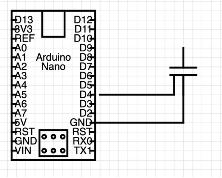
The last component, the magnet sensor (Figure 10) is fairly straightforward. Also programmed with a yaml file, the Magnet sensor has two parts to connect, and one side has two wires. These wires were stripped and taped to some extenders for a better connection. One wire was then plugged into the ground pin on the arduino and the other on the D4 pin. Once configured with programming, the arduino will be able to detect whether the sensor is closed or open with a high (open) or low (closed) reading.
To connect the devices to Home Assistant, the Home Assistant UI needed to be used. The Arduino IDE did not need to be used at all with this lab as all functionality is done through Home Assistant.
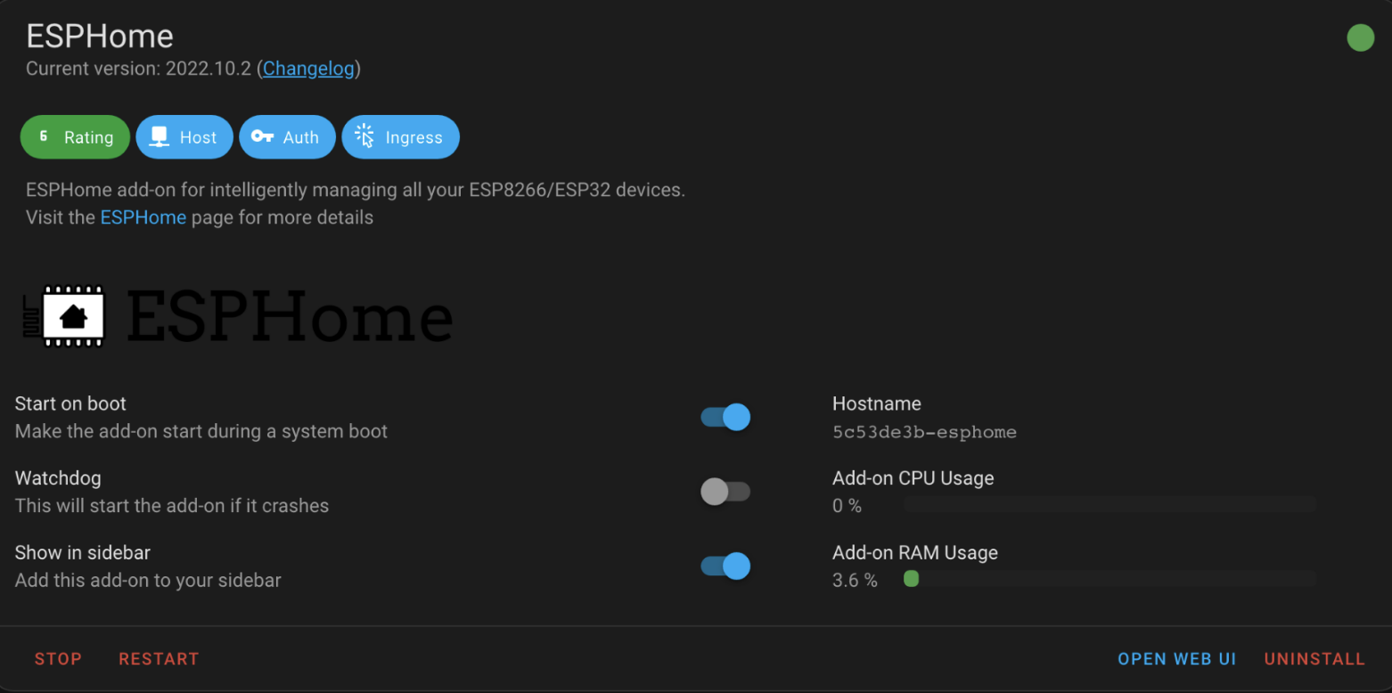
There are multiple possible approaches for connecting all of the devices, but for this lab, esphome was used. Esphome is added to Home Assistant as an “add on”. In the settings tab, there is a choice for add ons and by navigating to that page and browsing the add on store, the esphome add on can be found. After installing, the UI for esphome should be able to be viewed through a button on the esp home add on page (figure 12) and there is also an option to add to the side bar for easier access.
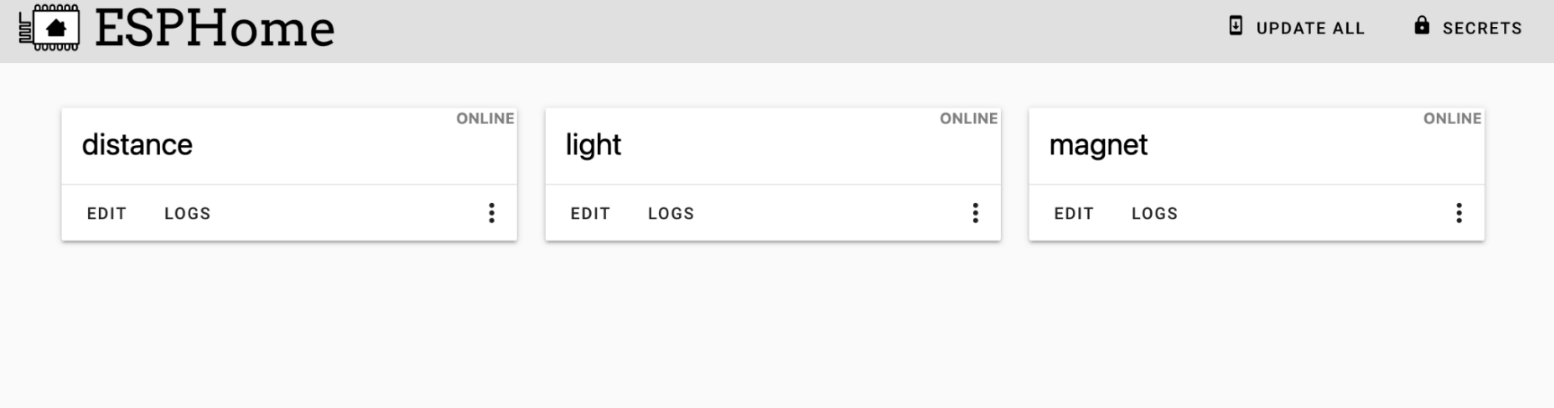
From the ESPHome panel (figure 13), there is an option in the bottom corner to add a new device. After naming it and choosing the correct board, it will be added to the ESPHome page as seen above. By pressing edit, there will be a yaml file (see appendix) that is editable to configure the Arduinos. The functionality of the Arduinos should not be coded here, only the set up. Install the yaml using one of the four available methods and copy the encryption key here to add the device to Home Assistant.
After navigating to settings -> devices, there should be an option to configure the device added. It will ask for the encryption key, and after, it may be added to the main dashboard for Home Assistant.
The last piece is getting the different devices to talk to one another. There is a section in settings titled “automations and scenes” and this is where the functionality will occur (figure 14).
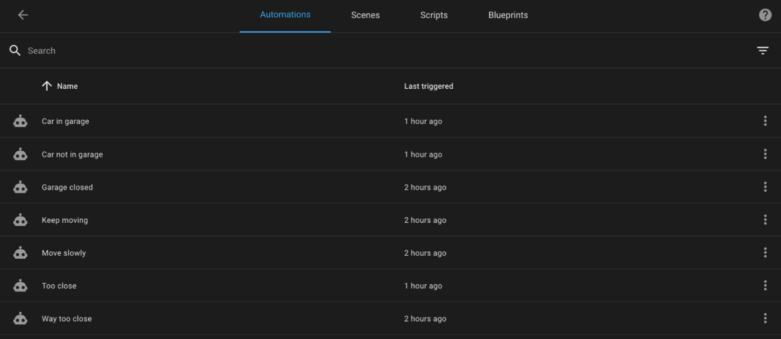
Here, different automations can be created for each state of the system. For example, Figure 15 shows the automation for turning on the green light at a reasonable distance.
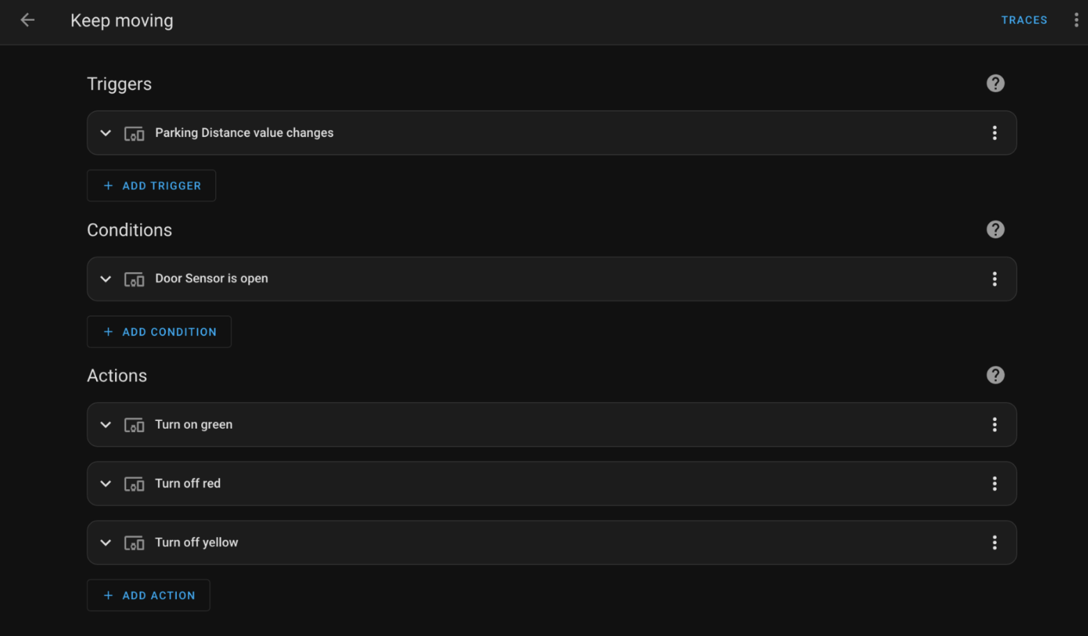
The trigger is when the distance of the distance sensor reads between 0.29m and 0.4m. The condition is that is will only trigger if the magnet sensor/garage door is open, and the actions turn on the green lights, and turn yellow and red off.
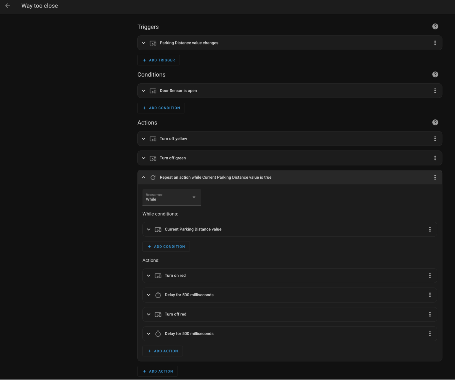
Most of the automations are very similar to the previous example, but there is one notable difference. The “way too close” automation needs a loop to flash the red LED. The trigger and condition is the same, but for actions, the unneeded lights turn off and then the red turns on, waits 500ms, turns off, waits another 500ms, and then repeats until the distance for blinking light is no longer relevant.
- Which version of Home Assistant did you choose to install? (Home Assistant Operating System, Home Assistant Container or one of the more experienced versions) Why did you choose this version?
- I used the Home Assistant OS installed on the raspberry pi. Initially I was going to integrate my MQTT broker that was already installed on the pi, so I tried to get the docker container working. I got it running, but there were many issues, one of which didn’t allow me to add any add ons to the UI which was needed for the labs.
- How should you decide which logic to perform in Home Assistant versus coding the logic directly into the devices? What guiding principles would you establish for future devices?
- I decided to do just about all of the coding on the home assistant. Since I decided to use ESPHome instead of MQTT broker, the Home Assistant software could handle all the functionality in a much nicer way. One example of this is the blinking light. It is much easier to not have to worry about looping and have something else take care of it for me.
- What features do you like the most about Home Assistant?
- I like how easy it is to create functionality between devices. It is very convenient to see everything remotely and to be able to control certain aspects from afar. I also like having everything set out in front of me. Much nicer user experience than the MQTT broker where all you can read is command line text.
- Please estimate the total time you spent on this lab and report
- 7-8 hours
This lab is the work of Anaïs Dawes. Any resources used are listed below in “References”.
Getting Home Assistant installed and working: https://www.home-assistant.io/getting-started/
Installing Home Assistant on Pi: https://www.balena.io/etcher/
Getting ESPHome running: https://iotdesignpro.com/projects/getting-started-with-esphome-how-to-install-and-integrate-with-home-assistant
Communication troubleshooting: Berin Hamilton, IT&C student
GPIO pins: https://randomnerdtutorials.com/esp8266-pinout-reference-gpios/