Step by Step Guide
ATTENTION: This guide is currently under development and incomplete.
IMPORTANT: All information here without guarantee and at your own risk!
- 3 small wires,
- a USB-to-UART adapter for 3.3V (e.g. from Amazon)
- Soldering Iron
- a Linux system (e.g. Ubuntu 20.04) or a VM with it (e.g. VirtualBox)
- the HxD Hex-Editor
- SD-Card fitting your CAM
- Card-Reader fitting your SD-Card
- a tool to copy a raw image from an SD-Card
- Open the bottom of your CAM.
- Identify the UART port:
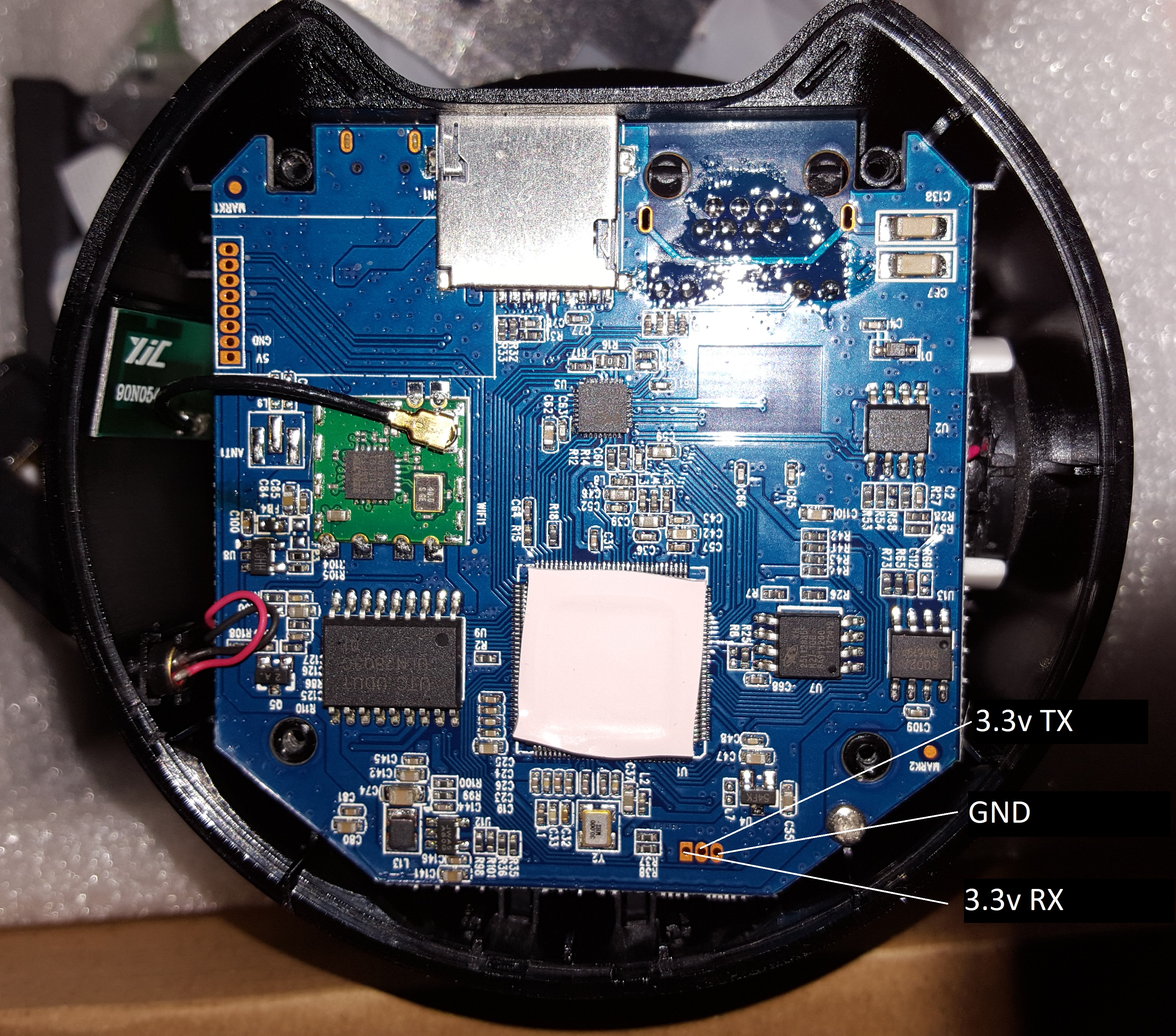
- Locate the serial port (see picture). The exact location can vary, but it number and order of the pin usually does match.
- Solder the wires to the PCB and connect it to the UART-USB adapter. Depending on the labeling of your adapter you may have to connect RX of the adapter with RX of the cam and vice versa
- Open a terminal app, and set the baud rate to 115.200bps, 1 stop-bit, 8 data-bit and no party check (SW neither HW).
For the step it might be helpful to get a second pair of hands. Depending on the settings of uboot the timeout may be set to 0. I also observed that connecting the serial port before powering up can prevent the CAM to boot. In this case you need to the following to get access:
- Unplug the UART from the adapter
- One should power the CAM
- While another one shall immediately connect the UART wires AND
- within one second (or even lesser) presses Ctrl+C in the terminal app.
A successful "break in" looks like this:

-
Insert the SD-Card into the CAM and give the device some time to settle.
-
Read the complete 16Mbyte flash into RAM at
0x2000000, this may take a few seconds:sf read 0x02000000 0 1000000 -
Copy the data from the RAM to the SD-Card
mmc write 0x02000000 0 0x8000 -
You should get something like this:
MMC write: dev # 0, block # 0, count 32768 ... 32768 blocks write: OK -
Eject the card from the CAM and insert it into your card reader.
-
Take care: Windows may now complain about a non-formatted device – don't format it by canceling the dialog.
-
Copy the SD -card with an appurtenant tool (e.g. HDD Raw Copy Tool (Windows), Roadkill Disk imager (Windows), dd (Linux), ...). Once the tool copied over 16MB you can abort the copy process.
There are two ways to gather the partition data:
- Via Boot dump/messages or
- by Analyzing the image.
-
Connect the UART adapter to your CAM. If your CAM doesn't want to boot with the adapter being connected, you'll have to wait little while after powering the CAM before connecting it, usually its about 1 to 2 sec.
-
Let it boot. At a specific point you'll see something like this rushing by:

- The MTD partitions are what we are looking for. The End of the first partition, here called "UBOOT" is the start of the second partition "LINUX".
- Be aware that the end addresses are part of the subsequent partition. In our example the start of the second partition is at address
0x060000. So, the last data address of the of the first partition is one address below0x060000, so0x05FFFF. - The size of a partition is the end address minus the end address.
- Open the sd-card image file in HxD via menu "Extras" – "Open disk image…". The editor will suggest a sector size of 512, and that's fine for us, so just confirm.
- Set the "Bytes per line" to toolbar to 20. That makes reading the partition table much easier.

For several steps it's important to know the exact size of the table as we are going to replace the USER0 partition with our own data. The start address of the first partition is located from 0x16 to 0x18 (highlighted range)

I'm not jet sure what the rest of the bytes does. It looks like the size of the partition is in Byte 0x20 and 0x21, but a trailing byte would be missing. Maybe something like Endianness? Not sure jet.

So the 1. partition starts at address 0x010000. The start addresses of the second partition can be found below the first address, and so on. Finally, we get the following data:
Start address 2. partition 0x060000, called "LINUX"
Start address 3. partition 0x300000, called "FS"
Start address 4. partition 0x900000, called "USER0"
Start address 5. partition 0xFF0000, called "USER1"
If we expect the size being in byte 0x20 and 0x21 and add a trailing byte, we get the following for size of 1. partition 0x050000. The End Address is calculated as follows: Start address + size -1 = end address. Doing this for all addresses we get the following table:
Whatever way you follow, according our example we get the following table:
| Part Nr. | Start | Size | End |
|---|---|---|---|
| 1 | 0x010000 | 0x050000 | 0x05FFFF |
| 2 | 0x060000 | 0x2A0000 | 0x2FFFFF |
| 3 | 0x300000 | 0x600000 | 0x8FFFFF |
| 4 | 0x900000 | 0x6F0000 | 0xFEFFFF |
| 5 | 0xFF0000 | 0x010000 | 0xFFFFFF |
You can test your results by continue investigation of the image. If you jump to 0x010000 you should find the start of the data of the first partition. Usually the previous area is not filled up and so some empty can be found. (indicated as subsequent bytes filled with 0xFF). It should look something like this:

Our target is the USER0 Partition, in this example starting at 0x900000 and ending 0xFEFFFF at. We need now to copy the data to a single file. I did this using HxD.
- Open the image file, if not already done
- Go to "Edit" and "Select Block…"
- enter the start and end address from the USER0 partition (Remember: The end address is the start address minus one). In our example Start =
0x900000and End =0xFEFFFF. - Press "OK" – now the related data is selected.
- Right click on the selected blocks and chose "Copy"
- Press Ctrl+n to create a new file
- Insert the content by Ctrl+v – you'll get a warning – confirm it by pressing "OK"
- Check if you copied the right stuff.
- Save the file.
For this step I highly recommend to use any Linux. If so, you'll need the kernel modules mtdram and mtdblock available on it. I used Ubuntu 20.04 desktop.
- Copy the file to linux
- Open a terminal or console.
- load mtd and mtdblock with the following commands:
sudo modprobe mtdram total_size=xxx, where xx must match your partition size (take the size, convert it to decimal and divide it by 1024). In our case it's the size is 16319: sosudo modprobe mtdram total_size=16319 - Load the block driver, by executing
sudo modprobe mtdblock - Copy the file into the new created mtdblock:
sudo dd if=/path/to/user0.img of=/dev/mtdblock0 - Create a working directory
mkdir fs - Mount the block device. The Image is a JFFS2 file-system:
sudo mount -t jffs2 /dev/mtdblock0 ./fs - Enter the directory
cd ./fs
- You can enable telnet by creating a empty file called "flag_debug_telnet", doing this:
touch ./flag_debug_telnet. these will allow you to connect to your CAM via telnet, port 9527 (telnet ip-of-the-cam 9527). - You can enable the development mode by creating an empty file called "flag_debug_dev_start", doing this:
touch ./flag_debug_dev_start. Be aware, that it will prevent the CAM from fully starting up - but you'll be able to access the CAM via the UART adapter without password. just enterrootas username at the login prompt.
NOTE: The CAM is configured to set the root password to a random string periodically. This prevents one from login in via telnet or the console, if the development mode is not activated. To workaround this and get permanent root access, without the development mode being activated, see the instructions under "Workaround to gain root access" below.
- Leave the working directory
fs. - Unmount the file-system
sudo umount /dev/mtdblock0 - copy the data back into a image file:
dd if=/dev/mtdblock0 of=/path/to/user0new.img - Format your SD card with FAT32 and but the changed file back on it.
- Connect again to the CAM, following the steps under "Connect to the device"
- Insert the SD card into the device
- execute the command
mmc rescan - Load the file from the SD card into RAM
fatload mmc 0:1 2000000 user0new.img: if this command fails try this one:fatload mmc 0:0 2000000 user0new.img. - update the flash memory from RAM with the following command
sf update 2000000 xxx yyy, wherexxxis the start address of the USER0 partition andyyyis the size of the USER0 partition. In our example it would look like thissf update 2000000 900000 6F0000You'll see a output tell you how many bytes have been updated, how many (unchanged) bytes have been skipped, etc.. - Eject the sd card and reset the CAM be un- and re-plugging the power of it.
Once you activated the development mode you can create a script, which resets the root password periodically.
- Activate the development mode
- login to the device and change to /dev_data by executing
cd /dev_data - run the following script (copy and paste it to the terminal, press enter after the last line)
echo "#!/bin/sh" >>dev_pwd.sh
echo while true >>dev_pwd.sh
echo do >>dev_pwd.sh
echo   echo setting root pwd to root >>dev_pwd.sh
echo   "echo \"root:root\"|chpasswd" >>dev_pwd.sh
echo   sleep 10 >>dev_pwd.sh
echo done >>dev_pwd.sh
echo  >>dev_pwd.sh
echo "/mnt/mtd/dev_data/dev_pwd.sh &" >>dev_init.sh
echo >>dev_init.sh
- execute
chmod +x /mnt/mtd/dev_data/dev_pwd.shto make it executable - execute
reboot, wait a few seconds and unplug the CAM - powre the CAM again
Now you can login via UART adapter / terminal app or if you created the file for telnet via
telnet ip-of-the-cam 9527. You may have to try several times. It's a competition between the reset script above the and script randomly changing the the password.