- Mikrocontroller STM32F303CBT6 is a processing unit
- Data acquisition system is provided by PILC company
- The data acquisition system consists of ADC, AHRS, GPS and recorder
- TowerPro SG-90 servos deflect the control surfaces (4 servos used)
- Supply voltage is realized usiong RHINO Li-Po battery
- Additionally, a radio receiver HK-TR6A V2 is connected to the microcontroller board (only during manual flights)
- Making a model of the rocket control system in the matlab\simulink program and generating code
- Using Discovery board as a programmer
- Devices communicate with each other via CAN bus
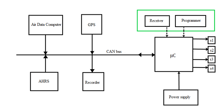
Figure 1 Hardware structure of the designed rocket control system
In the figure 1, hardware structure is performed. In the green frame there are devices that aren't used during automatic flight. The symbols s1, s2, s3 i s4 denote serwomechanism. Devices communicate with each other via CAN bus.
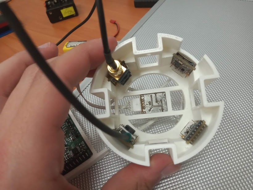
Figure 2 Container with measuring sensors
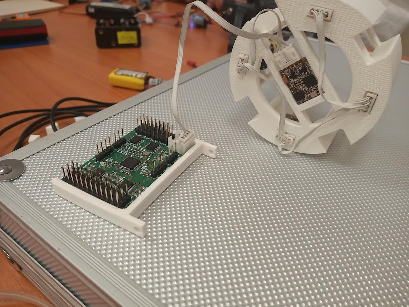
Figure 3 Sensors connected to the microcontroller via the CAN bus
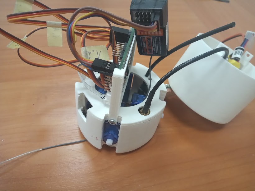
Figure 4 Control system with connected radio receiver
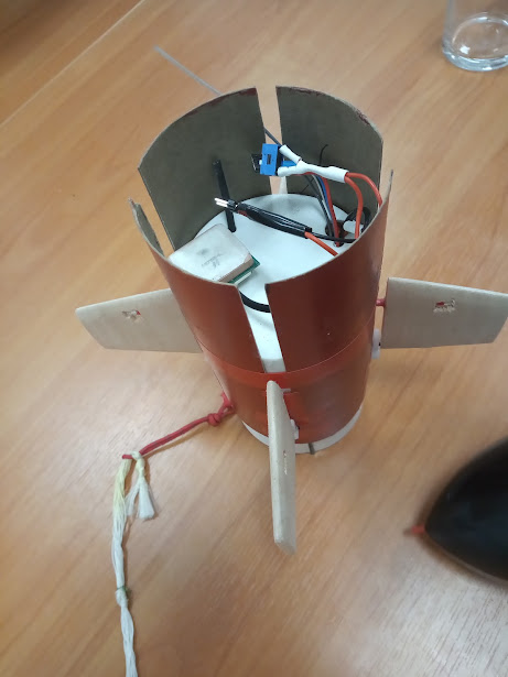
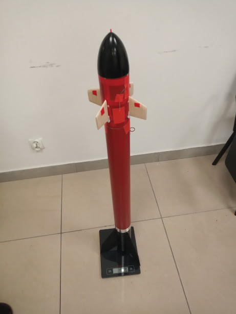
Figure 5 Control system with mounted control surfaces and rocket view
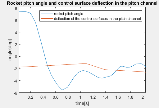
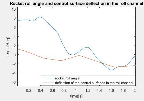
Figure 6 Rocket attitude and control surface deflection
Figure 6 shows the results obtained during the automatic fligh. A change in the position of the rocket was observed when the deflection of the control surfaces was changed. The rocket was initially placed at an angle of approximately 7.5 degrees to the vertical.