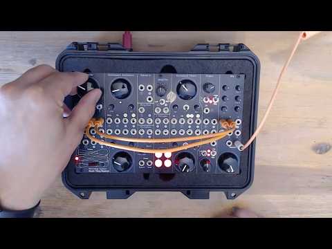
Knots is a 6 oscillator firmware for the Music Thing Workshop System.
Video overview:
Note: This is the write-up about building this thing. If you just want the user guide <- click that.
This all started because I wanted a hardware additive oscillator that can change the frequencies of the partials. Something similar to the centroid dissonance effect on Native Instruments' Razor. I was considering the Xaoc Odessa when I saw the CDM article about the Music Thing Workshop System. It's been out for a while and I was surprised it was new to me. It seemed like a cool device, the kit form was cheaper than the Odessa (and easier to justify). Plus I enjoy doing the DIY builds. So I gave up on my additive oscillator idea and bought that instead.
After it arrived from Thonk, I set aside a Saturday to do the build.
Aside: My build had 2 dry joints that needed to be fixed. One on the top filter's resonance pot and one on the lower Oscillator's FM pot. Resoldered those and it all worked.
After playing with the Workshop System for a while I realised that, in theory, it would be possible to make that additive oscillator idea. I took a look at the repo and saw that Python was an option. My Python skills are good enough to make what I want, however performance-wise, to make this work with lots of input modulation and MIDI, it would have to be C++. Python would still require an interpreter and is just not up to the task. I have not written any C++ in ages, and even then it was minimal. Writing optimized DSP code requires years of C++ experience. Experience that I don't have and, honestly, I'm not going to put in the time to obtain.
But...
There are AI coding tools and the current generation are very good at writing code.
Aside: Generative AI is a divisive topic. Some of the companies and the people who run them seem to not care about any of the consequences of the job losses or environmental impact they cause. This write-up is not going to tackle the ethics of using AI.
After cloning the repo, prying the main knob off, putting in a blank card and plugging a USB cable, I was ready to jump in to see how well this would work.
The initial step was to get the build chain running and test that it could build a deployable firmware. With that working, the first attempt was to try a version of the Plaits additive oscillator. This failed to work. After a few iterations of a prompt + build + test routine, I got it mostly working. But more importantly, it was working C++ code that was generating usable sounds coming out of the outputs.
The next step was to stand on the shoulders of giants and see what is possible and understand what could done.
The Computer board has limited compute power, certainly less than my MacBook and it's not optimized for audio like the Plaits is. It can do a lot, but there are limits. And limitations can be great for creativity.
The key limitation is floating-point arithmetic. There is a great video essay on the topic. Modern DSP algorithms rely on compute-heavy calculations, making floating-point arithmetic essential. But the Music Thing Workshop System is based on the RP2040 board, which does not have a hardware floating-point unit. Doing division as part of an algorithm adds extra load on the processor and the result will have errors. The RP2040 does fixed-point arithmetic well, which is much faster and with the right approach is more than enough.
I learned about these limitations by going through the examples and other releases in the Workshop_Computer repo and the Utility-Pair repo.
Note: Chris Johnson, who owns the Utility-Pair repo, also wrote the excellent ComputerCard implementation for the Workshop System.
There is a lot you can learn by going through some of this code, as there are a lot of optimisations that work well on the RP2040. It's such a useful resource that I added instructions in the AGENTS files for the coding agent to look in that source code for implementation ideas first.
For example:
uint32_t __not_in_flash_func(rnd12)()
{
	static uint32_t lcg_seed = 1;
	lcg_seed = 1664525 * lcg_seed + 1013904223;
	return lcg_seed >> 20;
}
That is how you generate random enough numbers in C++. I did not know any of this when I started!
Even without a floating point unit, the RP2040 is still very capable and has a few tricks to get more performance:
-
Dual Core
The RP2040 has 2 cores, allowing Knots to run audio generation on one core and the control processes on the other. Doing this split helped a lot with performance. -
Overclocking
The default CPU clock speed for the Workshop System is 133MHz, but it's certified to run at 200MHz. Close to double the performance.
After getting to grips with the limitations and where to find optimised C++ code and examples, I tried building my additive oscillator idea again. Part of this learning meant spending time with the excellent Twists, a port of Mutable Instruments Braids, and figuring out if it would be possible to make the additive oscillator. Getting that right meant it would be possible to make other oscillators. Borrowing the switchable oscillator idea from Twists, I decided to give a bigger implementation a go. Six interesting oscillators with lots of control.
These are the design criteria I landed on for the overall build and for each oscillator (which are called engines because that's what they're called in the Plaits repo). The main criterion being working within the performance constraints of the RP2040 and the layout of the Computer module’s I/O.
Use these engines
I'm working on a specific music project and want to use the Workshop System as the main sound design source. These engines need to be something I will use. The engines must have interesting timbres and usable ranges for the control parameters. I settled on a mix of engine ideas, with some inspiration from other devices and some adjustments to fit with Knots.
Invite patching
This has to be built to work with the rest of the modules on the Workshop System. It's not an isolated oscillator, it's part of a set of tools that can interact with each other to provide a much bigger sonic palette. This applies to all the inputs and outputs for the Computer module. The design should lend itself to patching with the filters, oscillators and slopes from the Workshop System. This should apply to Eurorack in general too. Make it a useful part of an overall sound design workflow.
Always have two related outputs
The Computer module has 2 audio outputs, the mixer has 2 pannable inputs and I have 2 ears. This seems almost pre-ordained. All 6 engines must have dual outputs that will operate as 2 independent, mono sound sources or as an interesting stereo source when panned.
Create two variations on the engine’s timbre
One of the cool features of the Plaits is the Aux out. It's a differentiated output version for the current engine. However when using both outputs for stereo, there is no spare "Aux" out. By using the Z switch, the module can have an alternative (Alt) mode which should implement a differentiated version of the engine. This gives a broader sonic palette.
Enable remote sequencing and control
This idea is borrowed directly from Twists and goes back to the original design criteria: “use the engines”. Configuring the USB port as a class-compliant MIDI interface means I can connect it to Ableton or the Ableton Move and sequence notes and control things.
The ComputerCard.h file "is a header-only C++ library, providing a class that manages the hardware aspects of the Music Thing Modular Workshop System Computer." It wires up the ins and outs of the Computer module in sensible ways to make it easier to use them from the start, without having to worry about the complexity of writing this code yourself. It's extremely helpful and something coding agents should use. It lets the agent sessions focus on sound generation and control and not on the detail of managing I/O, which has its own quirks and gotchas.
The ComputerCard implements a specific layout for the input and output jacks:
- 2 x Audio Ins and Outs
- 2 x CV Ins and Outs
- 2 x Pulse Ins and Outs
You don't have to use it this way though, and this implementation repurposes the 2 audio ins as CV ins. The rest are kept as is. It's a great layout.
The main knob is used for tuning the main oscillator of all the engines. It's a 10 octave span from 10Hz to 10KHz, clamped at either end so CV or MIDI input won't push it past those min and max values. After trying different values for the range, this felt the most usable. It does get a bit noisy at higher frequencies for some of the engines, but I like it. Plus I'm old, so while my dog doesn't appreciate the aliasing, I don't notice it :)
The X and Y trimmers adjust 2 parameters exposed by the engines. These differ per engine and, in some cases, are different in the Alt mode. The parameters are musical to encourage their use.
Below the X and Y trimmers are the two audio inputs. This layout lends itself to using those audio inputs as CV inputs for the X and Y trimmers. The ComputerCard has a function Connected(Input::Audio1) that will allow different code to run if there is a cable connected to the input jack. If there is a cable connected, the X and Y trimmers become attenuators for the CV signal on the input cable. These Audio inputs run at control rate, not at the full audio rate.
Both the Audio and CV inputs can accept values from -6 V to 6 V. This is clamped to -5 V to 5 V in the code though. The Slopes modules, when running in Loop mode with nothing connected to the input, will output 0 V to 12 V. This is not ideal and this is a mismatch that would normally be solved using the input trimmers as attenuverters, not attenuators. However the built-in SineSquare Oscillators do map to the ±6 V range and sound great as modulators. There is an easy workaround for the 0-12 V issue discussed in the CV I/O section.
The X trimmer has an additional function used in conjunction with the Z switch.
The Z switch does 4 things:
- In the middle position, the module is in the Normal mode, with normal outputs on Audio Out 1 + 2
- In the up position, the module is in the Alt mode, with alternative outputs on Audio Out 1 + 2
- Pushing the momentary switch down and returning to the middle will move the engine to the next slot, and change the LED.
- Note: the change happens when you release the Z switch, not when you push it down, to allow for the clock stuff.
- Holding the switch down and moving the X trimmer will adjust the speed of the clock output from Pulse Out 2.
Tip: The term to stop a switch from being jittery or just continuously changing while it's being held down is debouncing. If you want to implement something similar, tell the coding agent to use "debouncing" for the momentary switch.
Audio Out 1 and 2 are the two outputs for the module and will either output the Normal mode or Alt mode, depending on the Z switch position.
The repurposed Audio In 1 + 2 for the X/Y CV is explained above. The remaining CV I/O is:
CV In 1
A 1 V per Octave CV input
connected to the main tuning. It works relative to the Main knob position but doesn't exceed the 10Hz - 10KHz range limit.
Tip: It's fun to connect the SineSquare Oscillators to this input. However there is no attenuator for it, but you can pass the oscillator's output through the Stompbox section and use the Blend knob to attenuate the signal. CV In 1 runs at control rate - approx 1kHz - so you can get FM-ish sounds this way but it's not full on FM.
CV In 2
CV In 2 is a VCA, an idea taken from Twists but implemented differently. It acts like a standard VCA for both outputs, but you need to provide the gate/envelope. The input responds to signals in the 0-5 V range. Zero and below mutes both outputs. 5 V and above (up to the 6 V limit) sets unity gain for the outputs. It's also set to unity gain if nothing is plugged in.
There is a configurable slew in the code that prevents the VCA from sounding too clicky when getting gate inputs. Look for kVCAGainSmoothShift, if you want this to be faster or slower, or tell your coding agent to do it.
Note: the Ring Mod can also be used as a VCA, but then you don't get stereo and you no longer have a ring modulator. This frees it up for additional weirdness!
Tip: Patching Pulse Out 1 to CV In 2 with USB MIDI will gate the outputs to note on/off messages. And if you patch Pulse Out 1 into a slope input and then into CV In 2, you can create variable envelopes to shape the start and end of the notes.
CV Out 1
This passes the MIDI note out in 1 V per Octave format. This is independent of the Main knob or CV In 1 so it's a direct MIDI to CV mapping, using the CVOut1MIDINote() function from the ComputerCard, which is the calibrated output. Handy for sending MIDI sequences to other oscillators.
CV Out 2
CV Out 2 is a secret weapon! The main connection is to MIDI CC 74, so you can send control messages from your DAW/MIDI sequencer and control anything that accepts a -6 V to 6 V input. MIDI CC is limited to 128 steps, so it might be a bit too jagged for precision requirements.
When the module restarts or the MIDI CC 74 value is set to 0, it will output -6 V which can be very useful on the Workshop System.
Tip: The SineSquare Oscillators can become LFOs if you patch the -6 V coming out of CV Out 2 into the Pitch In. They will run a lot slower!
Tip: The Slopes are a type of variable slew rate limiter and you can change them from the default 0-12 V output to -6 V to 6 V range by patching the -6 V coming out of CV Out 2 into the Slope input, not the Slope's CV In. This does change the rate when in Loop mode and I’m not sure why. This is useful for getting another LFO that works well with other CV inputs on the Computer module.
The bottom row of jacks is the Pulse section. These inputs are simple.
Pulse In 1
When plugged in it overrides the Z up/middle position setting and switches the module between Normal mode with a low input (0 V) and Alt mode with a high input (5 V).
Pulse In 2
When plugged in it overrides the Z momentary down/middle position setting and advances to the next engine on each new rising edge (0 to 5 V).
Tip: Connecting the SineSquare Oscillators square outputs to these Pulse inputs gets very interesting!
Pulse Out 1
This follows the MIDI gate on/off, going high (5 V) while the note is held.
Pulse Out 2
This is the other secret weapon. Pulse Out 2 is a clock output that can drive sequencers, delays or just make interesting rhythmic patterns. The speed of the clock can be adjusted by holding the Z switch down and turning the X trimmer. Once you've turned the X knob while holding Z down, the engine slot won't advance when you release Z.
The clock rate goes from 20 - 999 BPM. If there is a MIDI clock present at the USB MIDI interface, the clock output will follow the MIDI clock and the X knob changes the divisions applied.
| Division | Rate |
|---|---|
| 24 | 1/4 note |
| 12 | 1/8 note |
| 8 | 1/8 note triplet |
| 6 | 1/16 note |
| 4 | 1/16 note triplet |
| 3 | 1/32 note |
| 2 | 1/32 triplet |
| 1 | raw 24 PPQN clock |
The output is a ~5ms, 5 V pulse for each clock tick. This was tested with a Moog DFAM and it drives the sequencer as expected!
Tip: Plugging Pulse Out 2 output into a Slope input lets you keep the tempo of the Slope output but adjust the slope's angles for interesting rhythmic timbre changes.
The USB input is simply a class-compliant MIDI interface. It only does MIDI note value, on/off and MIDI CC 74. The note value is a "last note wins" implementation. The CV Out 1 and main tuning keep the last value too. The MIDI input is hardcoded to MIDI channel 1, but you can change this and recompile the firmware if you want something else, ask your coding agent!
This shows the currently selected engine and flashes briefly when receiving MIDI notes.
Note: I came up with these names after a few beers and some fine Dutch herbs. Not my best work but I stand by them.
All the engines use one or more phase accumulators as the main source oscillator, setting the frequency. They either use the phase position to select the output value from a lookup table, with some interpolation to create the output waves, or generate ramps or stepped outputs for saws and square waves. With some anti-aliasing where applicable, see the individual engines for details.
It's a supersaw implementation with 7 saw waves spread across the stereo field.
Normal Mode
This is the saw wave mode, with 7 saw waves made using a wrapping phase accumulator, which creates a ramp, with bandlimiting to deal with aliasing. The saw uses PolyBlep to deal with aliasing at higher frequencies, something I learned when working on this code.
The 7 saw waves are spread out as follows.
| Voice | Tune | Pan | Gain |
|---|---|---|---|
| 1 | -106.8c | -0.8999 | 0.5000 |
| 2 | -63.8c | -0.6001 | 0.7000 |
| 3 | -24.2c | -0.3000 | 0.8501 |
| 4 | 0.0c | 0.0000 | 1.0000 |
| 5 | +27.3c | +0.3000 | 0.8501 |
| 6 | +67.6c | +0.6001 | 0.7000 |
| 7 | +91.3c | +0.8999 | 0.5000 |
X controls the stereo spread between the two outputs and Y controls the amount of detune. Both go from 0 at full CCW to the values in the above table at full CW.
Alt Mode
This is a super triangle mode, which is the same thing but with triangle waves. The triangle waves are made using the saw wave generation process and a per-voice leaky integrator. “A what” you ask? See the Agent Coding section for some details on this.
X and Y do the same thing.
A combination wavefolder and bitcrusher.
Normal Mode
2 sine waves using the SineLUT function are generated with one wave going through a wavefolder to Audio Out 1 and the other going through a bitcrusher to Audio Out 2. The code for both of them was borrowed from Utility-Pair.
X is the amount of folding and Y is the amount of crushing.
Alt Mode
In Alt Mode the wavefolder is routed through an additional bitcrusher first before going to output and vice versa.
X is the amount of folding for both folders and Y is the amount of crushing for both bitcrushers.
A wavetable oscillator with 2 wavetables based on 16 x 256 sample AKWF single-cycle waves. One wavetable per mode, i.e. Normal and Alt modes use different wavetables.
You move through wavetables (with interpolation) using the X and Y knobs, sending the X position to output 1 and Y position to output 2. This creates an interesting stereo field.

The original idea was to have 2 different wavetables per mode going out each output, 4 in total for both modes. Unfortunately the reads from flash via XIP were too much and caused it to glitch. Something I learned about during this whole process.
The actual wavetables used were created using a web-based tool made with the coding agent that lets you browse through, filter, audition and assemble your own "curated" wavetable. See the floatable wavetable creator folder.

This took an evening to make while dual screening a show and is surprisingly fun to use. If you don't like the wavetables being used, use the tool to make your own or tell your coding agent to use whatever wave files you like. Convert it to the required header format and rebuild the firmware.
This is the original additive oscillator idea. This borrows most of the fundamental design ideas from the Plaits Harmonic Oscillator, which is a bump and slope implementation with 24 partials. This implementation uses 16, which is about the max the RP2040 can reasonably handle.

It consists of 16 phase increment oscillators whose frequencies follow the standard harmonic series from the fundamental, each generating a sine wave using the SinLUT() function.
There was some complexity managing the overall output gain to keep a constant perceived volume as the gain of the individual partials changes. There was a lot of back and forth with the coding agent to get this right.
Normal Mode
X moves the bump from the first partial to the last. This is interpolated between partials to be smooth, but it can sound like it's stepping when the slope is steep. Y sets the slope from very steep at full CCW, where only the 2 partials closest to the bump position are active, to flat at full CW, where all partials have the same gain.
Well .. approximately that at either end. Making it exactly flat or only using 2 partials would require extra calculations for an already busy oscillator. At the midpoint of Y, the partials follow a
Alt Mode
Alt mode implements a "centroid" feature that can change the frequencies of the partials. Using the bump, i.e. the X position, as the central point, Y will modify the partial frequencies to move in toward the bump position going CCW and move out to the edges (partial 1 and 16) going CW. Try it, it sounds very cool!
I have a very old and somewhat road-worn Nord Modular Micro that was my introduction to the world of modular synthesis.

It has both a vocal oscillator and vowel filter that sound great and I wanted to make something similar. The initial idea was to get this to work by putting 2 bandpass filters set to the vowel formant frequencies after a saw wave. This didn't have the depth of vowel-like sound that the Nord does. The Twists/Braids VOWL oscillator is much closer to that Nord sound, so I got the coding agent to implement that.
The concept is 3 formant oscillators running at fixed frequencies. There are 2 x sine waves, using SinLUT(), and a square wave using SquareQ12(). These are running at the 3 formant frequencies for the specific vowel sound we want to make. For A it's a sine wave at 609Hz, another at 1000Hz and the square running at 2450Hz. These are then summed/mixed together at gain values of 1, 0.5 and 0.251 respectively. The frequency and gain values vary per vowel and there are tables with all these values in the code.
There is also the primary phase increment ramp oscillator, with its frequency attached to the Main knob and other frequency modifiers, known as the "glottal envelope" that does 2 things:
- It applies amplitude modulation to the 3 summed formant oscillators.
- It resets the phase of all 3 of the formant oscillators every time it wraps, like oscillator sync.

This gives the impression of an overall fundamental frequency being applied to the 3 formant oscillators that can be shifted around while keeping the underlying vowel consistent. By changing the frequency and gain values of the formant oscillators independently from the main glottal envelope, you get the singing voice timbre of the Losenge engine.
Normal Mode
This runs the 3 formant oscillators at F1, F2 and F3 for the associated vowel. Note: This is the mapping for a male voice
| Vowel | F1 (Hz) | F2 (Hz) | F3 (Hz) |
|---|---|---|---|
| A | 609 | 1000 | 2450 |
| E | 400 | 1700 | 2300 |
| IY | 238 | 1741 | 2450 |
| O | 325 | 700 | 2550 |
| U | 415 | 1400 | 2200 |
X morphs the formant frequency and gain values between the vowels, moving from A > E > IY > O > U over the range of the knob for Audio Out 1 and the inverse sweep (U > O > IY > E > A) for Audio Out 2.
Y changes the F1 value but keeps the ratios between them the same, which changes it from sounding darker/lower at full CCW to brighter/higher at full CW.
Alt Mode
This is the brighter upper-formant table. It replaces the base F1/F2/F3 set with an upper F2/F3/F4 value.
| Vowel | F2 (Hz) | F3 (Hz) | F4 (Hz) |
|---|---|---|---|
| A | 1000 | 2450 | 3300 |
| E | 1700 | 2300 | 3500 |
| IY | 1741 | 2450 | 3300 |
| O | 700 | 2550 | 3400 |
| U | 1400 | 2200 | 3300 |
An early iteration used the frequency mapping for a female voice for Alt mode, but it didn't sound that different to Normal mode when keeping the fundamental glottal envelope frequency the same.
Where Bender is the distortion module, this is the noise module. Both modes are based on an oscillator that morphs between a sine wave and saw wave using SinLUT() and PolyBlepSawQ12() respectively.
Normal Mode
In Normal mode the transition is an interpolation between the 2 waves with added noise. X controls the position between the 2 waves. Sine wave at full CCW and a saw wave at full CW. As you move X the interpolation point moves between the sine wave and saw wave with a random variation around the interpolation point. The midpoint of X is halfway between the 2 waves and starts sounding like pitched noise.
Y changes the noise from low-passed noise at full CCW for a smoother, more controlled sound, to high-passed noise at full CW for a jittery, buzzy sound.
For Audio Out 2 the saw wave is phase shifted 90 degrees to give a sense of widening stereo as you move X.

Alt Mode
In Alt mode the output switches between a sine wave and saw wave randomly, but only when the waveform cycle repeats. This way you will always either get one full sine wave or one full saw wave, randomly chosen.
X biases the randomness towards the sine wave going CCW and towards the saw wave going CW. The midpoint is 50/50. Y is the rate of switching, or rather how long a wave is held before it's allowed to change. From slow blips at full CCW to flickering at full CW.
The workflow is divided into 2 phases: building a solo version of the engine first and then combining it with the main Knots code. All the scaffolding and instructions are in the AGENTS files and skills to let the coding agent know how to follow this workflow. Tell it you want to build a new solo engine and your general idea and it will create all the bits you need.
In solo engine mode only the Main, X, Y and Z switch (for Alt mode) are enabled. No MIDI or other inputs / outputs are used. It's a slightly quicker build path to keep testing new or changed engines without breaking the main Knots build. Once you are happy with your solo engine, the coding agent can bring it back into the Knots code and compile firmware for you to test.
Note: the full knots adds more control overhead than the solo engine, so busy engines may work in solo mode but glitch in full knots mode. This happened a few times and is annoying.
As I said at the start, there is no way I would have made this without a coding agent. I lack the required C++ coding experience and don't want to allocate the time to learn it only to make synth modules. So I took this shortcut.
There are multiple coding agents available, using different models and implementation frameworks, and there are many, many strong opinions about which ones are the best. They are all converging towards the same point though and most of them should be good enough to help you create new modules. I experimented with a few but ultimately landed on Cursor.
The mental model I use for these agents is to think of them as an engineering intern that has severe amnesia and has to re-read everything about the project from the start every time you ask them to do something. They just get up to speed each time very quickly. This isn’t a conversation in the human sense. Every response requires the agent to re-read the context. It's not a person, it’s a token generator that does a good job of writing code.
One of the goals of this project is to make the repo as usable as possible for any coding agent. I saw this pull request, which has useful additions that were also added to the agent files.
It's worth reading through the AGENTS.md and AGENT_REFERENCE.md files and the files in the skills folder.
.ai
└── skills
    ├── mtws-oscillator-design
    │   ├── references
    │   │   ├── design_checklist.md
    │   │   └── repo_map.md
    │   └── SKILL.md
    ├── ...
Despite all of this documentation to help the coding agent write good code, it's still going to make major mistakes and be wrong about things. There were 2 major challenges doing this:
-
If some new code introduced a bug or glitch, it could be something created a few steps back but went unnoticed. Coding agents will keep iterating and trying to fix from where you are now in the code. An agent can fixate on finding a solution and try several approaches that will break other things. Roll back and test incrementally.
-
When hearing CPU overload glitches or issues that were clearly bugs, the agent would confidently say that's an artifact of the oscillator type and it’s expected to hear it and fixate on that being the problem.
When that fixation happens, get the coding agent to update your TO-DO and tracker docs and start a new chat session.
As said earlier, I don't have C++ experience, but still I had to read and figure out code to get past issues the coding agent was not able to. Having it explain things I did not know or understand and compare the code that did not work with examples and references that did help a lot. It's well worth digging into the code and getting past the vibes.
These are the learnings from using the coding agent during this process:
- It will be wrong, often
- You can run the clock at 200MHz safely despite its claims
- Use the AGENTS files to stop the coding agents doing things you don't want them to
- Get it to make tools to help your understanding and to do useful stuff
- Make it comment code so you can understand it later
- If it persists with a wrong claim during a session, start a new chat
The most useful part in all of this is that I now know way more about C++ DSP code and how oscillators are made than I did when I started.
Be curious, read the code and ask the coding questions!
Things I asked the coding agent:
- How is triangle in the alt mode for sawsome generated?
- Explain to me how this
tri_state_[voice_index] -= tri_state_[voice_index] >> 11creates a triangle? - What is XIP?