- Hello_CircuitPython
- CircuitPython_Servo
- CircuitPython_LCD
- Motor Control
- Temperature Sensor with LCD screen
- Rotary Encoder with LCD screen
- Photointerrupter
In this assignment, we just started doing code with circuit python, and our assignment was to make the onboard neopixel red. The main focus of the assignment was to learn how to connect a board and getting familiar with the syntax of CircuitPython.
import board
import neopixel
import time
import math

Dot = neopixel.NeoPixel(board.NEOPIXEL, 1)
Dot.brightness = 0.1
print("Make it red!")
while True:
    Dot.fill((255,0,0))
Connecting to the Arduino actually took an incredible amount of time. Because the libraries were not built in, getting them in or replacing the libraries was very complicated. I learned a lot about what it takes to actually connect a board up, and even just getting that little light to turn red was a big victory. Also, in this time, I realized that circuitpython is a lot similar to C++ but with more adaptability for libraries. If I did this assignment again I would cheat off other people a lot earlier, because I spent a while just flondering while the people next to me actually knew what to do.
Using circuitpython,connect to a servo and rotate it 180 degrees and back using buttons. The focus of this assignment is to learn how to use servos, and just generally learn how to use electronic parts with the metro.
import board                       #[1-16] Setup for Buttons
import time                        #And servo
import math
import pwmio
from adafruit_motor import servo
from digitalio import DigitalInOut, Direction, Pull
btn = DigitalInOut(board.D3)
btn2 = DigitalInOut(board.D2)
btn.direction = Direction.INPUT
btn2.direction = Direction.INPUT
btn.pull = Pull.UP
btn2.pull = Pull.UP

pwm = pwmio.PWMOut(board.D5, duty_cycle=2 **15, frequency=50)
myServo = servo.Servo(pwm)

print("starting")
while True:                 #[17-27]If a button is pressed
    print("re")             #Rotate to either 180 or 0
    if btn.value == True:
        myServo.angle = 180
        time.sleep(1)
        print("Right")
    elif btn2.value == True :
        myServo.angle = 0
        time.sleep(1)
print("Left")| Evidence | Wiring |
|---|---|
 |
 |
Using PWMio I connected an object to the 3 pin. What that means, I have no clue, but thats how it works. Thanks to This Site for that information. From there, it's fairly simple to just use the adafruit motor library function .Servo(). If I could do this assignment again, I probably would have just googled it a lot earlier and then I wouldn't have spent so much time trying to figure out the code myself.
import board
import math
import time
from lcd.lcd import LCD                                     #[4-14] code to connect
from lcd.i2c_pcf8574_interface import I2CPCF8574Interface   #input pins to board
from digitalio import DigitalInOut, Direction, Pull
i2c = board.I2C()
lcd = LCD(I2CPCF8574Interface(i2c, 0x27), num_rows=2, num_cols=16)
btn = DigitalInOut(board.D3)
btn2 = DigitalInOut(board.D2)
btn.direction = Direction.INPUT
btn2.direction = Direction.INPUT
btn.pull = Pull.UP
btn2.pull = Pull.UP
num = 0                         #Display Variable
Redo = True                     #[16-17] Variable to "debounce" button

lcd.print("Starting")
while True:                                 #[19-30] Code to add and subtract
    if btn.value == True and Redo == True:  #from variable and
        if btn2.value == True:              #"debounce" the  #buttons.
            num = num - 1
        else:
            num = num + 1
        lcd.clear()
        lcd.print(str(num))
        Redo = False
        time.sleep(.1)
    elif btn.value == False and Redo == False:
Redo = True| Evidence | Wiring |
|---|---|
 |
 |
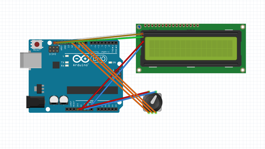
Using some libraries, I connected the LCD screen and the buttons (Which was much harder than I expected). For the first button I had to "debounce" the counting button, and then the second button was a single if statement to tell it to count up or down. I feel like I had a pretty good grasp of this asssignment, as I had done one that was just like it in engineering 2, however I did get stuck on something for 30 mins when I only had to add .value. If I had to do this assignment again, I would have actually read the directions so I wouldn't have to redo the entire code because I did the wrong thing.
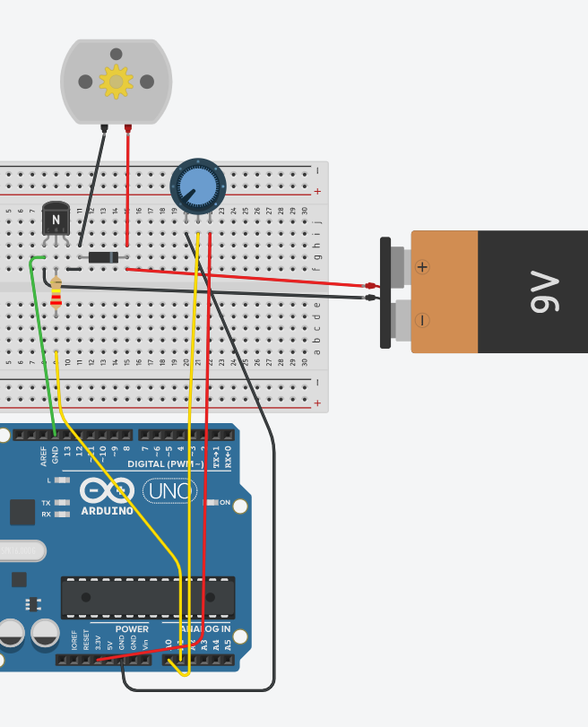
Using a transistor and an external battery pack, control a DC motor. The learning target of this assignment was to learn how to use a transitor as well as relearning how to create analog outputs in the neww coding language.
import board               #[lines 1-4] Importing neccesary libraries
import time
from analogio import AnalogOut, AnalogIn
import simpleio

motor = AnalogOut(board.A1) #[lines 5 & 6] Definining the motor and potentiometer
pot = AnalogIn(board.A0)

while True:
    print(simpleio.map_range(pot.value, 96, 65520, 0, 65535)) #Print mapped potentiometer value to motor inputs
    motor.value = int(simpleio.map_range(pot.value, 96, 65520, 0, 65535)) #Write the mapped value to motor
time.sleep(.1) #So that the serial monitor works| Evidence | Wiring |
|---|---|
 |
 Credit for image goes to Lucia Whitmore Credit for image goes to Lucia Whitmore |
In this assignment, I actually learned a lot. More than just how to wire a DC motor or use a battery pack, but a few things about workflow:
- Give up. Don't just keep trying at something you can't do, however, ask and you will recieve
- In wiring, it is the best thing to go through where the current will flow, thinking out if the wiring will do what is intended
- In code, it is the best thing to immediately google your assgnment, and only start coding once you have gotten a hold on the material.
Overall, this assignment was really annoying for me, as I don't enjoy the finicky nature of either code or wiring, and multiple times I just was missing one detail that made my entire thing not work. If I did this assignment again, I would review my notebook from last year to look for tips in wiring.
Using a LCD and Temperature sensor, display a message based on the temperature of the room. The learning target of this assignment was to learn how to use a Temperature sensor, and also deal with the problem of the LCD breaking the Metro.
import board   #[Lines 1-8] Importing all Neccessary libraries to communicate with LCD
import time
from lcd.lcd import LCD
from lcd.i2c_pcf8574_interface import I2CPCF8574Interface
from digitalio import DigitalInOut, Direction, Pull
import board
import analogio


# get and i2c object
i2c = board.I2C()
tmp36 = analogio.AnalogIn(board.A0)
# some LCDs are 0x3f... some are 0x27.
lcd = LCD(I2CPCF8574Interface(i2c, 0x27), num_rows=2, num_cols=16)
def tmp36_temperature_C(analogin):              #Convert millivolts to temperature
    millivolts = analogin.value * (analogin.reference_voltage * 1000 / 65535)
    return (millivolts - 500) / 10


while True:
    # Read the temperature in Celsius.
    temp_C = tmp36_temperature_C(tmp36)
    # Convert to Fahrenheit.
    temp_F = (temp_C * 9/5) + 32
    # Print out the value and delay a second before looping again.
    lcd.set_cursor_pos(0, 0)           #[Lines 26-36] Print different messages based on the temperature
    if temp_F > 75:
        lcd.print("it's too hot!")
    elif temp_F < 70:
        lcd.print("it's too cold")
    else:
        lcd.print("It's just right")
    lcd.set_cursor_pos(1, 0)
    lcd.print("Temp: {}F".format(temp_F))
time.sleep(.5)| Evidence | Wiring |
|---|---|
 |
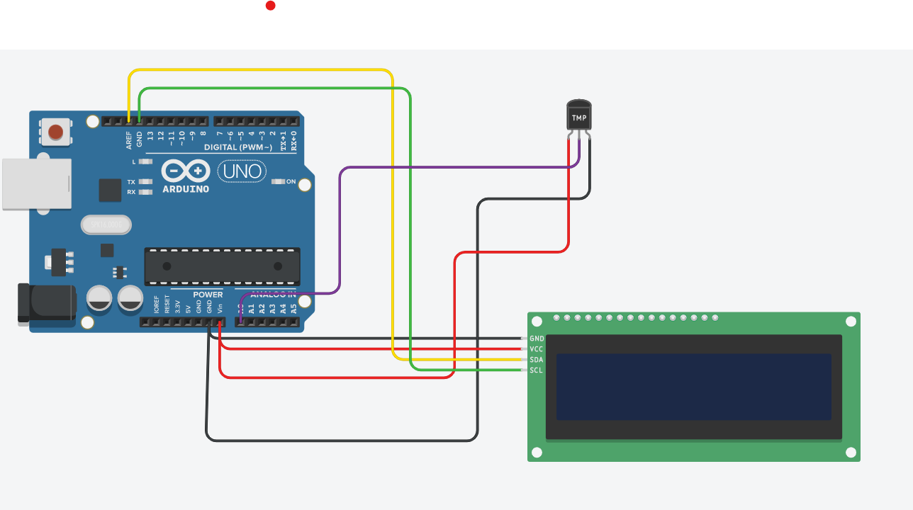 Credit for image goes to Graham Gilbert-Scroder Credit for image goes to Graham Gilbert-Scroder |
This assignment was not that interesting, honestly. It was simply a regurgitation of previous assignments, and even the temperature sensor, which I thought would be interesting was just an analogRead. The one interesting thing was the cool formating that you can do on a LCD screen, like in this case using a {} to represent a changing variable. This made the LCD less blockish to work with and also made it look better.
Using a LCD and three lights, create a working stoplight menu that changes the lights when pressed. The learning target of this assignment was to learn how to use rotary encoders, and use a varible with different Cases.
# Rotary Encodare light thingksf;ja             # [lines 1-7] Import and set up neccesary libraries
import time
import rotaryio
import board
from lcd.lcd import LCD
from lcd.i2c_pcf8574_interface import I2CPCF8574Interface
from digitalio import DigitalInOut, Direction, Pull


encoder = rotaryio.IncrementalEncoder(board.D3, board.D2) # [lines 9-24] Start all Variables and define INs and OUTs
last_position = 0
btn = DigitalInOut(board.D1)
btn.direction = Direction.INPUT
btn.pull = Pull.UP
state = 0
Buttonyep = 1


i2c = board.I2C()
lcd = LCD(I2CPCF8574Interface(i2c, 0x3f), num_rows=2, num_cols=16)


ledGreen = DigitalInOut(board.D8)
ledYellow = DigitalInOut(board.D9)
ledRed = DigitalInOut(board.D10)
ledGreen.direction = Direction.OUTPUT
ledYellow.direction = Direction.OUTPUT
ledRed.direction = Direction.OUTPUT


while True:                #[lines 27-38] Set up varible for encoder, limit it to >0 and <3
    position = encoder.position
    if position != last_position:
        if position > last_position:
            state = state + 1
        elif position < last_position:
            state = state - 1
        if state > 2:
            state = 2
        if state < 0:
            state = 0
        print(state)
        if state == 0:     #[lines 39-47] Print to LCD based on Encoder Var
            lcd.set_cursor_pos(0, 0) # [39
            lcd.print("GOOOOO")
        elif state == 1:
            lcd.set_cursor_pos(0, 0)
            lcd.print("yellow")
        elif state == 2:
            lcd.set_cursor_pos(0, 0)
            lcd.print("STOPPP")
    if btn.value == 0 and Buttonyep == 1: #[lines 48-63] If the button is pressed make the Encoder Var match the lights.
        print("buttion")
        if state == 0:
                ledGreen.value = True
                ledRed.value = False
                ledYellow.value = False
        elif state == 1:
                ledYellow.value = True
                ledRed.value = False
                ledGreen.value = False
        elif state == 2:
                ledRed.value = True
                ledGreen.value = False
                ledYellow.value = False
        Buttonyep = 0       #[lines 64-68] Resets and delay
    if btn.value == 1:
        time.sleep(.1)
        Buttonyep = 1
last_position = position| Evidence | Wiring |
|---|---|
 |
 Credit for image goes to River Lewis Credit for image goes to River Lewis |
This assignment was more in depth, and I feel I learned something using rotary encoders. What exactly that was, I don't know, but I think that if I needed to use them in the future it would not be incredibly hard. Also, there was a problem with the I2c LCDs that hung me up for about a week. The metro wouldn't connect if I plugged it in with the LCD, so I needed to disconnect it and reconnect without the LCD.
Using a Photointerrupter and time.monotonic(), count how many times a photointerrupter has been triggered. The learning target of this assignment was learn how to use time.monotonic() and relearn how to use a photointerrupter.
import time            # [lines 1-3] Import necessary libraries
import digitalio
import board

photoI = digitalio.DigitalInOut(board.D7)
photoI.direction = digitalio.Direction.INPUT
photoI.pull = digitalio.Pull.UP

last_photoI = True
last_update = -4

photoICrosses = 0

while True:
    if time.monotonic()-last_update > 4:
        print(f"The number of crosses is {photoICrosses}")
        last_update = time.monotonic()

    if last_photoI != photoI.value and not photoI.value:
        photoICrosses += 1
last_photoI = photoI.value| Evidence | Wiring |
|---|---|
 |
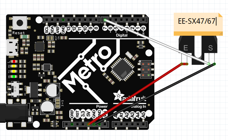 |
| Credit for Wiring and Video goes to Graham Gilbert Scoeder |
This assignment was not hard, because I stole the code from River Lewis and the wiring was, to say it in a more complex than the wiring itself, so easy that a child could do it. time.monotonic was the hardest concept, but since River did it for me, I didn't need to worry about it at all. I would also like to add the fact that time.monotonic was entirely useless on this assignment, and that River used it like delay().