
Replies: 2 comments

|
Hey there! From those symptoms it does seem like the interface to the Apple II bus is not working right. If you have an oscilloscope then probing pin 31 on the Pico must show a clean regular clock signal, which is the Apple bus clock that the Pico firmware uses to time the bus reads. If this signal is messy then you can get garbled output like you are seeing. I'm not 100% familiar with the retrotink designed boards but it looks like they use a resistor instead of a logic gate for that clock signal to translate from 5V to the Pico's 3.3V. Personally, I have not had good luck with high speed (over 200KHz) signal integrity when large resistors were on the signal line which is why I recommended checking that clock signal with a scope. One other thing to check could be the 74LVC245 chips themselves. Other logic families like 74LS will not work and if you got your chips from a less reputable source then there's a small chance they could be relabeled or counterfeit. You could probably tell if they're good or not by putting an oscilloscope probe on the output side (pins 2-9) and verifying that the voltages are reasonable 3.3V TTL logic levels with clean transitions. |

|
It's working! I just modified a number of abus.pio and finally it works! For information, My debugging log
uint16_t ptr = 0x400;

void putlogchar(uint8_t c) {
  main_memory[ptr] = c;
  if (++ptr > 0x800) ptr = 0x400;
}

void putloghex(uint8_t c) {
  putlogchar(c < 10 ? c + '0' : c - 10 + 'A');
}

void putlog(uint16_t addr, uint8_t data) {
  ptr = 0x400;
  putloghex((addr >> 12) & 0x0f);
  putloghex((addr >> 8) & 0x0f);
  putloghex((addr >> 4) & 0x0f);
  putloghex(addr & 0x0f);
  putlogchar(' ');
  putloghex((data >> 4) & 0x0f);
  putloghex(data & 0x0f);
  putlogchar(' ');
}

...

static void shadow_memory(bool is_write, uint_fast16_t address, uint32_t value) {
...
    case 0x2000 >> 10 ... 0x3c00 >> 10:
// *****************************************
// when access $2000.., print snooped address and data to $400, those will be shown on apple ii text mode screen.
      putlog(address, value);
// *****************************************
        // hires page 1
        reset_detect_state = 0;
        if(!is_write)
            break;
That's all folks. |




Uh oh!
There was an error while loading. Please reload this page.
Uh oh!
There was an error while loading. Please reload this page.
I recently got a PCB(retrotink version) and do soldering by myself. But it didn't work correctly.
So, I made my own version with prototyping PCB.
It still doesn't work. Same result.(no PCB problem)
It works with
RENDER_TEST_PATTERNtest pattern.(No VGA DAC problem)But, within My Apple //e enhanced, it shows weird screen.
This is the result when I run following basic program:
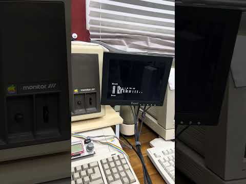
https://youtube.com/shorts/NP9JtHIC-q0?feature=share
As you see, something changes but incorrect address.(abus pio?)
Text mode only. No GR, HGR, PR#3 and so on. Maybe, it can't read soft-switches too.
I double&triple checked all wires and registerance and votages and so on.
I'd tried to debug it, It's toooooo fast with log.
(I saw some address and data bus was captured but I can't check whole logs)
What can I do further?
Any suggestions or advice would be appreciated.
All reactions