4 Hardware Setup
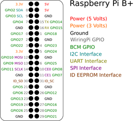
The project includes three main sensors and one FM Transmitter connected to the Raspberry Pi device. All sensors should be connected properly to correct pins via jumper cables. Sensors need power supply (5V or 3.3V), GND and signal pins. GPIO Pins can be used for transmitting and receiving data signals between Raspberry Pi and sensors on circuit. Pin scheme of Raspberry Pi 3+ is given below:
Following steps explain how to set up the project circuit.
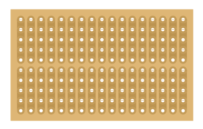
Project can be made any type of breadboard but 17x10 breadboard preferred in order to select maximum small breadboard. Breadboard helps to connect components on pins in same columns.
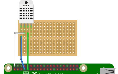
RHT-1 sensor is used in order to getting humidity and temperature information. This sensor has four pins: VCC, GND and Data signal. VCC pin should connected to 5V+ and GND pin should connected to any GND pin on device. Data signal pin is connected to GPIO-4 pin for this project.
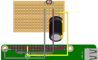
4.3 Light Sensor To measure environmental light level, an LDR sensor is used in project. LDR is simple device has two pins, use its resistivity to measure light level by using a 1 µF polarized capacitor for getting information. When one LDR pin connected to 3.3 V power on Raspberry Pi (not 5V, its important), the other pin of LDR should connect both (-) leg of capacitor and also to GPIO-3 pin. The positive (+) leg of capacitor should be connected to GND pin on device. The circuit for light sensor will show as following scheme:
Ultrasonic sound sensor is used for measure the distance between an object in front of sensor and device. The logic behind this sensor, measuring the time between the sound wave that send and received in a very small time. Total distance is calculated by divide this time interval by sound speed. Total distance is two times of distance, so we need to divide it by two, to find exact distance between object and sensor. The ultrasonic sound sensor should have connected to 5V power supply, GND and GPIO pins with jumper cables, resistors.
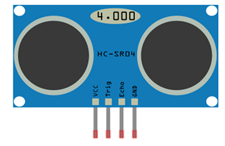
Echo pin is connected to GPIO-24 with a 220-ohm resistor and Trig pin is connected to GPIO-23. The following scheme is the final for all connections, including ultrasonic sound sensor:
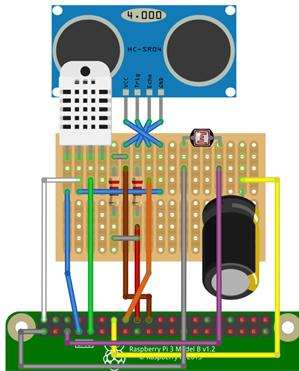
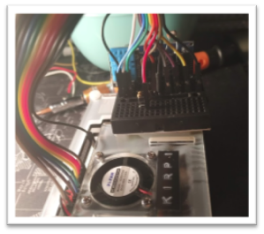
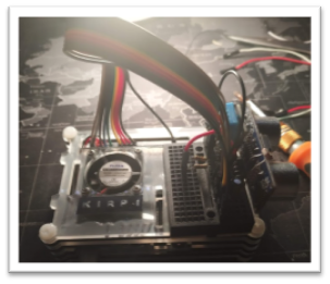
The circuit can be so complex but good wiring is a solution to effective work on circuit.
➡️ The Script