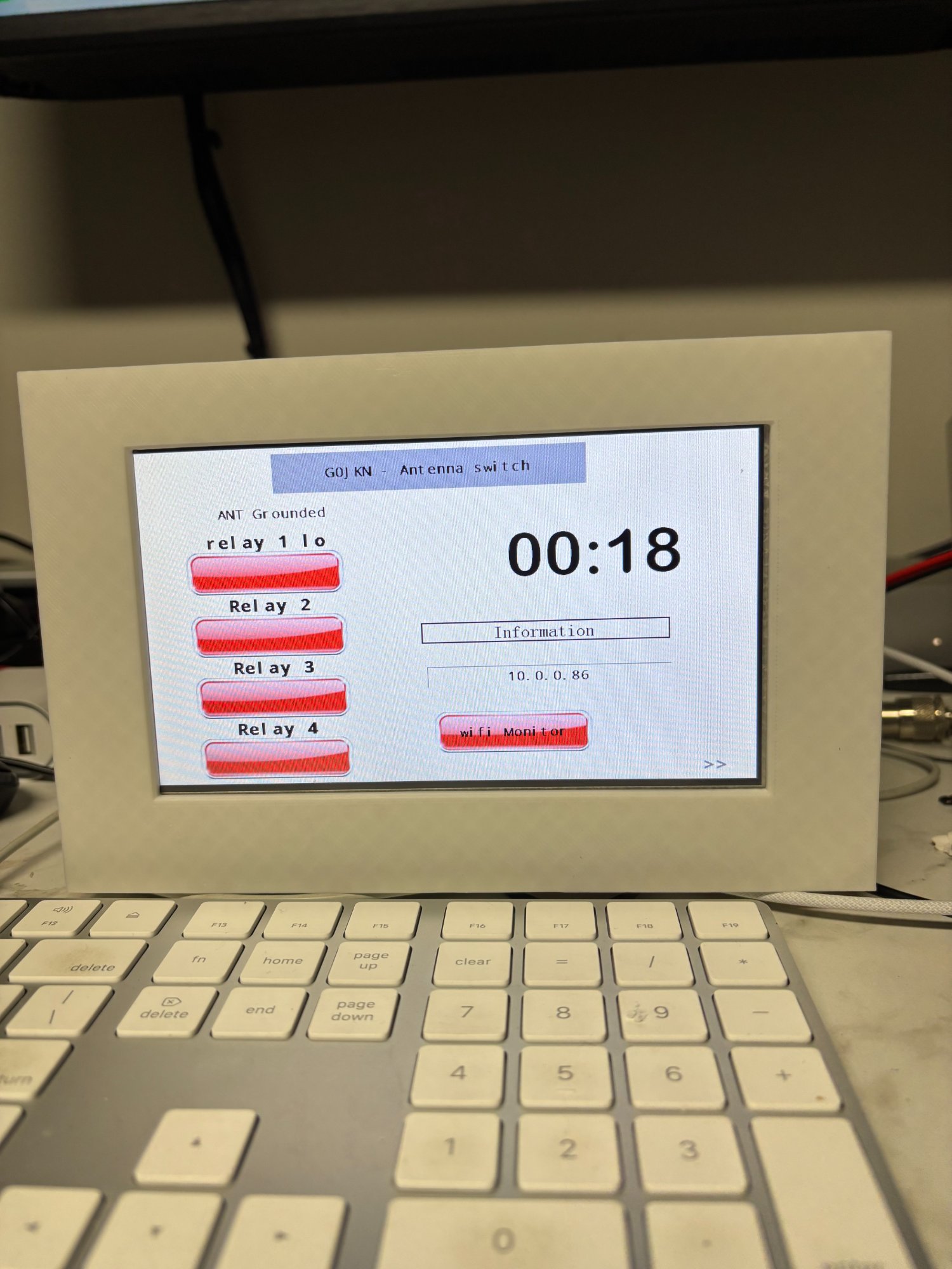
 Front panel — Nextion 3.5" touchscreen showing antenna ports, band display, SO2R status, NTP clock and IP address. 3D printed enclosure designed in Fusion 360.
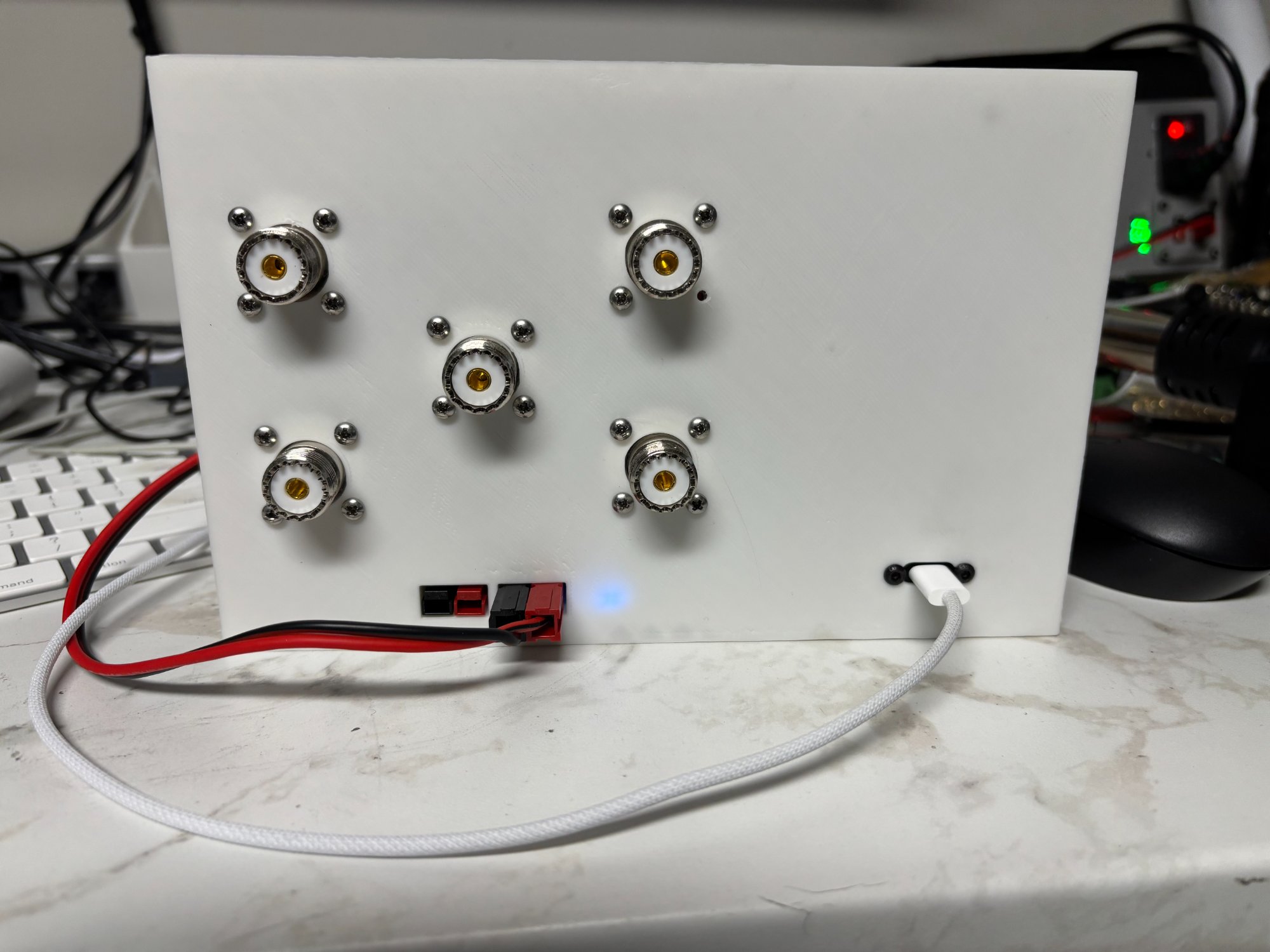 Rear panel — five SO239 connectors (one radio input, four antenna outputs), 12V DC power connector with XT60, and USB port for programming. Blue power LED visible.
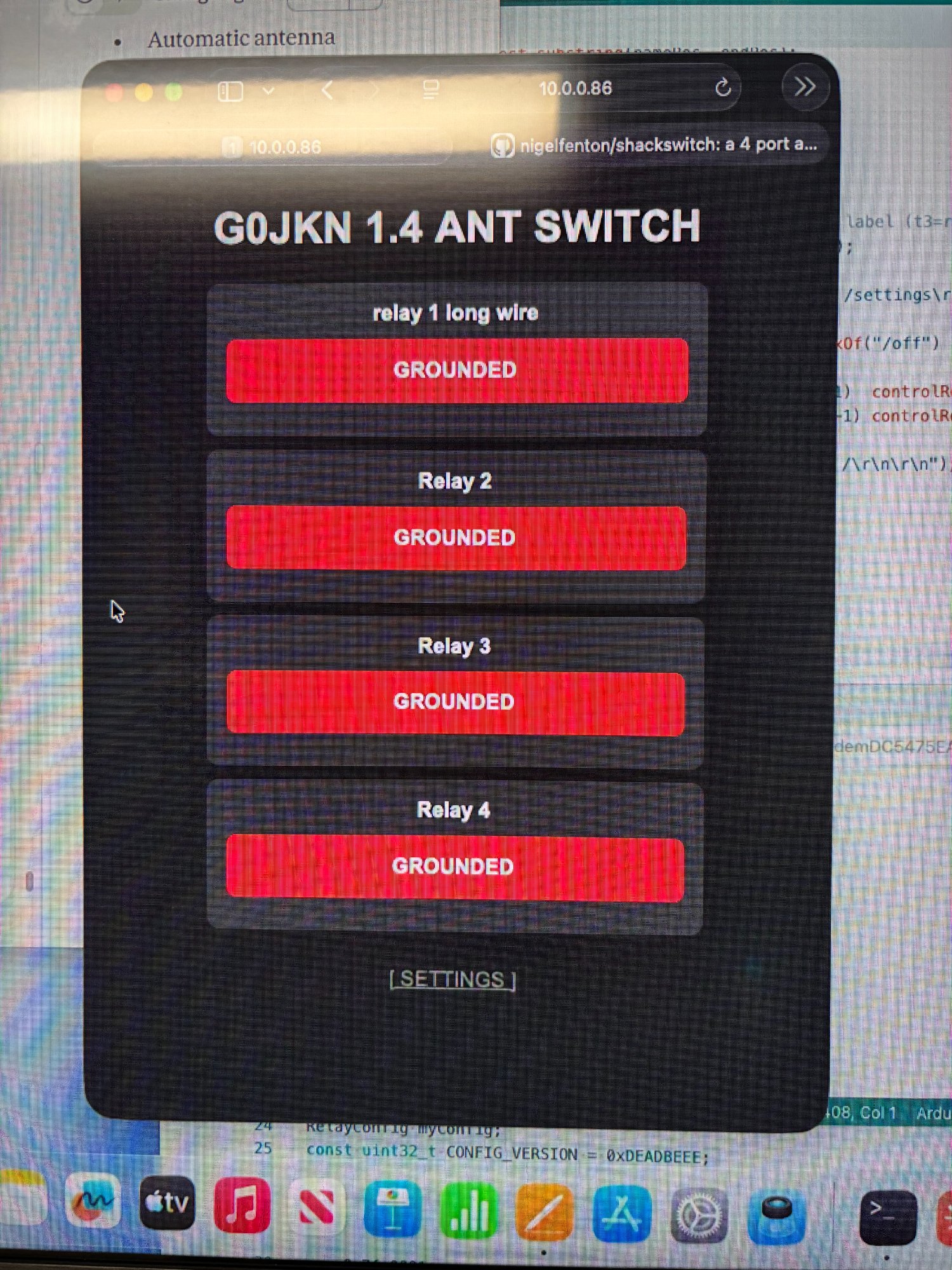 Web interface — four antenna ports with live band and SO2R status panel. Updates automatically every 5 seconds.
The G0JKN ShackSwitch is an open source shack controller designed and built by G0JKN as a hobby project. It started life as a simple 4-port antenna switcher and has grown into a full station management system covering antenna switching, SO2R interlock, automatic band tracking via FlexRadio SmartSDR, and network integration via a TCP control protocol and REST API.
If you are new to Arduino or amateur radio electronics, don't worry — this guide explains everything step by step. If you are an experienced builder, feel free to skip ahead to the sections most relevant to you.
- 4-port antenna switching — select between up to 4 antennas with a single button press
- Touchscreen control — Nextion colour display with dual-state image buttons
- Web interface — control and monitor the switcher from any browser on your network, including mobile devices
- Live web updates — relay state, band display and SO2R status all update automatically every 5 seconds
- Band display — tBandA and tBandB show current band for Input 1 and Input 2 on the Nextion and web page
- SO2R interlock — inhibits second input if both are transmitting on the same band or same antenna
- FlexRadio band tracking — automatic antenna switching driven by SmartSDR frequency data via Raspberry Pi Python service
- TCP control protocol — port 9008, compatible with AetherSDR and Node-RED integration
- UDP discovery beacon — auto-discovery by network clients every 5 seconds
- REST API — full HTTP endpoint set including /setband for band updates
- Antenna labels — each port displays its assigned antenna name on the touchscreen and web page
- WiFi connected — built-in web server, NTP time sync, and network integration
- LED Matrix display — shows active relay or grounded state on the Arduino's onboard matrix
- EEPROM storage — antenna names and WiFi credentials survive power cycles
- Factory reset — double-tap safety reset accessible from the touchscreen
- KK1L 2x6 relay board expansion — upgrades to 2-input, 6-output matrix via MCP23017 I2C expanders
- Additional shack switching relays (amps, lights, PSU remote) via MCP23017
- BCD band decoder input and output
- PA protection / sequencer integration
- AetherSDR native integration panel (issue #179)
| Component | Details |
|---|---|
| Arduino Uno R4 WiFi | The brains of the system — includes onboard WiFi and LED matrix |
| Nextion NX4832T035 | 3.5 inch colour touchscreen display (or similar Nextion model) |
| 4x relay module | Single pole, for antenna switching (one relay per antenna port) |
| Custom Arduino shield | PCB or veroboard shield carrying relays, transistor drivers and connectors |
| 12V DC power supply | Powers relay coils via the shield |
| Buck converter | Steps 12V down to 5V for the Arduino and shield logic |
| Raspberry Pi (any model) | Required for SmartSDR band tracking (runs smartsdr.py service) |
- 1x SO239 input (from radio)
- 4x SO239 outputs (to antennas)
The ShackSwitch sits between your radio and your antennas. Your radio connects to the single RF input, and each of your antennas connects to one of the four RF output ports. Pressing a button on the touchscreen (or clicking in the web interface) activates the corresponding relay, connecting that antenna to the radio and grounding all others.
Radio TX/RX
    │
    │  SO239 in
    ▼
┌─────────────────────┐
│  G0JKN ShackSwitch  │──── Relay 1 ──► SO239 ──► Antenna 1
│                     │──── Relay 2 ──► SO239 ──► Antenna 2
│  Arduino R4 WiFi    │──── Relay 3 ──► SO239 ──► Antenna 3
│  Nextion 3.5"       │──── Relay 4 ──► SO239 ──► Antenna 4
└─────────────────────┘
    │              ▲
    │  WiFi        │ HTTP /setband
    ▼              │
Web Browser    Raspberry Pi
               smartsdr.py
                   ▲
                   │ TCP port 4992
                   │
              FlexRadio SmartSDR
The ShackSwitch is architecturally a two-input device, reflecting the KK1L 2x6 expansion board and the FlexRadio dual-slice model:
- Input 1 = FlexRadio Slice A (TX capable)
- Input 2 = FlexRadio Slice B
In a two-radio setup, Input 1 and Input 2 map to Radio A and Radio B respectively. The firmware tracks band and TX state for each input independently.
A Python service (smartsdr.py) runs on a Raspberry Pi on the same network. It connects to SmartSDR on TCP port 4992, subscribes to slice frequency events, and calls the ShackSwitch /setband REST endpoint whenever the band changes. The Nextion display and web page update automatically.
When both inputs are transmitting simultaneously, the firmware evaluates interlock conditions:
- Same antenna conflict — Input 2 inhibited
- Same band conflict — Input 2 inhibited
The Nextion tSO2R component shows SO2R OK (green) or INHIBIT (orange).
Libraries required (install via Arduino IDE Library Manager):
EasyNextionLibraryby SeithanNTPClientby Fabrice Weinberg- WiFi, RTC, EEPROM, LED Matrix and ArduinoGraphics are included with the R4 board package
Upload:
- Open
shackswitch.inoandtriggers.inoin the Arduino IDE — both must be in the same folder - Select Tools → Board → Arduino Uno R4 WiFi
- Select the correct COM port
- Click Upload
Configure WiFi:
Edit the loadConfig() function defaults before uploading, or use the touchscreen WiFi config page after upload.
Important — boot order: Always apply 12V power before or simultaneously with USB. The Nextion runs from 12V — if the Arduino boots before 12V is connected, the boot-time display sync commands are lost.
Copy the .HMI file to a FAT32 microSD card, insert into the Nextion, and power the display. It flashes automatically. Remove the card when complete.
The smartsdr.py script connects to your FlexRadio and calls /setband automatically on band changes.
Install:
# Copy the script
cp smartsdr.py ~/.node-red/smartsdr.py

# Edit the IP addresses at the top of the file
nano ~/.node-red/smartsdr.py
# FLEX_IP = "your.flex.ip.address"
# SHACKSWITCH_IP = "your.shackswitch.ip.address"

# Install as a systemd service
sudo cp smartsdr-tracker.service /etc/systemd/system/
sudo systemctl enable smartsdr-tracker.service
sudo systemctl start smartsdr-tracker.service
Check it's running:
sudo systemctl status smartsdr-tracker.service| Endpoint | Description |
|---|---|
GET /status |
Returns relay states, bandA, bandB and so2r as JSON |
GET /[n]/on |
Activate relay n (1–4), ground all others |
GET /[n]/off |
Ground relay n |
GET /rename?id=[n]&name=[name] |
Rename antenna port n, persist to EEPROM |
GET /setband?input=[1|2]&band=[name] |
Set band for Input 1 or 2 (e.g. 40m) |
GET /settings |
Settings web page |
Example /status response:
{"r1":0,"r2":1,"r3":0,"r4":0,"bandA":"40m","bandB":"20m","so2r":0}Example /setband response:
{"input":1,"band":"40m","bandId":4,"so2r":false}The ShackSwitch listens for TCP connections on port 9008. Commands are prefixed C[seq]|, responses are prefixed R[seq]|code| or S0| for unsolicited events.
| Command | Description |
|---|---|
C1|ping |
Keepalive check |
C1|antenna list |
List all configured antennas |
C1|band list |
List all bands with frequency ranges |
C1|port get [n] |
Get full state of input port n |
C1|port set [n] rxant=[n] band=[n] |
Set port parameters and drive relay |
C1|interlock set radioA=[0|1] band=[n] |
Update TX state and trigger interlock |
A UDP discovery beacon is broadcast every 5 seconds on port 9008:
SS name=ShackSwitch serial=SS-001 version=1.5.0 ip=[IP] port=9008 ant=4 radio=2
| Arduino Pin | Nextion Pin |
|---|---|
| TX1 (Serial1) | RX |
| RX1 (Serial1) | TX |
| 5V | VCC |
| GND | GND |
| Arduino Pin | Function |
|---|---|
| D2 | Relay 1 (Antenna 1) |
| D3 | Relay 2 (Antenna 2) |
| D4 | Relay 3 (Antenna 3) |
| D5 | Relay 4 (Antenna 4) |
| Connection | Details |
|---|---|
| 12V DC in | Powers relay coils directly |
| Buck converter | 12V in → 5V out → Arduino 5V pin and shield logic |
| Component | Type | Purpose |
|---|---|---|
| b1 – b4 | Dual-state button | Antenna select (active/grounded image) |
| t3 – t6 | Text label | Antenna name above each button |
| tBandA | Text label | Current band for Input 1 / Slice A |
| tBandB | Text label | Current band for Input 2 / Slice B |
| tSO2R | Text label | SO2R OK (green) or INHIBIT (orange) |
| tState | Text label | ANT Active / ANT Grounded |
| tClock | Text label | Current time (NTP synced) |
| t1 | Text label | WiFi IP address |
Display shows "N O T C O N N E C T E D" Check SSID and password in the sketch, or use the touchscreen WiFi config page.
tBandA / tBandB show "---" after boot
Normal — no band data has been received yet. Start smartsdr.py on the Pi and change band in SmartSDR. The display updates within seconds.
Nextion shows default antenna names after reflash Boot order issue — ensure 12V is applied before or with USB power so the Nextion is ready when the Arduino runs setup().
Web page band panel not updating
Check /status returns bandA and bandB fields. If they show ---, the smartsdr.py service is not running — check with sudo systemctl status smartsdr-tracker.service.
SmartSDR band tracker not connecting
Confirm the FlexRadio IP address in smartsdr.py. Test TCP connectivity with nc -zv [flex-ip] 4992. Check SmartSDR is running with an active slice.
Web page not updating after touchscreen button press The web page polls every 5 seconds. Wait a few seconds — it will update automatically.
shackswitch/
├── firmware/
│   ├── shackswitch.ino           — main sketch, web server, TCP protocol, relay control
│   └── triggers.ino              — Nextion touch event handlers
├── nodered/
│   ├── smartsdr.py               — SmartSDR band tracker (runs on Raspberry Pi)
│   └── smartsdr-tracker.service  — systemd service file for auto-start on boot
├── nextion/
│   └── shackswitch.HMI           — Nextion Editor project file
├── hardwear/
│   ├── shield-schematic.pdf      — Arduino shield schematic
│   └── BOM.csv                   — Bill of materials
├── docs/
│   └── project-brief.docx        — full project brief and architecture document
├── images/
└── README.md
| Version | Changes |
|---|---|
| 1.0 | Initial release — basic 4 relay antenna switching, Nextion display |
| 1.1 | WiFi web server, web-based antenna control, EEPROM name storage |
| 1.2 | NTP time sync, station monitor page, factory reset, WiFi config page |
| 1.3 | Dual-state image buttons on Nextion |
| 1.4 | Antenna name labels, live JSON web updates, improved WiFi handling |
| 1.5 | TCP control protocol (port 9008), UDP discovery beacon, FlexRadio band tracking, SO2R interlock, /setband REST endpoint, Nextion band display, live web band panel, SmartSDR Python integration service |
This project is released as open source under the MIT Licence. You are free to use, modify and distribute it for personal or commercial purposes. Attribution to G0JKN is appreciated but not required.
Built by G0JKN — a retired amateur radio operator keeping the mind sharp one solder joint at a time. Designed in Fusion 360, coded in Arduino IDE, tested in a real HF shack with a FlexRadio 6700.
Feedback, suggestions and pull requests welcome. If you build one, please share a photo!
73 de G0JKN 📻