This project should emulate a controller with an Arduino board and play TAS on the Nintendo Switch.
Uses the LUFA library and reverse-engineering of the HORIPAD for Nintendo Switch for accurate controller emulation.
On June 20, 2017, Nintendo released System Update v3.0.0 for the Nintendo Switch. Along with a number of additional features that were advertised or noted in the changelog, additional hidden features were added. One of those features allows for the use of compatible USB controllers on the Nintendo Switch, such as the Pokken Tournament Pro Pad.
Unlike the Wii U, which handles these controllers on a 'per-game' basis, the Switch treats the Pokken controller as if it was a Switch Pro Controller. Along with having the icon for the Pro Controller, it functions just like it in terms of using it in other games, apart from the lack of physical controls such as analog sticks, the buttons for the stick clicks, or other system buttons such as Home or Capture.
The original version of the code that this repo is based off of emulated the Pokken Tournament Pro Pad, but changes have been made to support the HORIPAD wired controller for Nintendo Switch instead. In addition, many additional features/improvements have been added.
- A LUFA-compatible microcontroller such as the Teensy 2.0++, Arduino UNO R3, or the Arduino Micro
- A USB-to-UART adapter. In a pinch, an Arduino UNO R3 with the ATMega328p disabled (connect RESET to GND) will work.
- A machine running Windows or Linux. Mac should also be possible, but hasn't been tested.
Besides the Arduino you also need an UART to USB-Bridge. This one from Amazon works for me. You also need an HDMI- to VGA-Adapter and either a HDMI or VGA splitter to still view the output of the Switch while running the task; If your capture card has an mirroring output that works too.
First, you need to connect TX (pin 1 of the Arduino) to TXD (on the USB-UART bridge) and RX to RXD. Normally, you connect TX to RX, but we are using the ATmega16u2 in the Arduino, which inverses TX and RX.
Next, you have to wire the arduino to the VGA-output of the Switch. You need to connect PIN14 of the VGA-Connector to PIN3 of the first ICSP header (MISO-Pin, look at image below).


On these pictures, the blue wires are VGA-related, the red and white wires are TX-related and the black wires are RX-related.
After connecting the bridge to your PC, you can check which COM-Port it uses. Go into your "Device Manager" and check below "COM & LPT" for "Silicon Labs CP210x USB to UART Bridge (COM?)" (for my device, linked above). That ? after COM is your needed COM port. Note that the GUI should automatically detect the correct COM port.
In case you see issues with controller conflicts while in docked mode, try using a USB-C to USB-A adapter in handheld mode. In dock mode, changes in the HDMI connection will briefly make the Switch not respond to incoming USB commands, skipping parts of the sequence. These changes may include turning off the TV, or switching the HDMI input. (Switching to the internal tuner will be OK, if this doesn't trigger a change in the HDMI input.)
This repository has been tested using an Arduino Uno.
First of all, you need a Linux VM (for example in VirtualBox, tested with Ubuntu) or computer running Linux. Here you need to install the ArduinoIDE. Next, you edit the makefile and insert your installation dir at ARDUINO_PATH (keep the additions at the end to let it point to the correct dir).
After every restart of the Linux VM you need to extend the $PATH-Variable by running the following command: sudo export $PATH=(your ArduinoIDE-Installation-dir)/hardware/tools/avr/bin/:$PATH (also look if it points to an existing directory).
Now you should be ready to rock. Open a terminal window in the Arduino-subdirectory, type make, and hit enter to compile. If all goes well, the printout in the terminal will let you know it finished the build! Follow the directions on flashing Joystick.hex onto your Arduino, which can be found below.
You need the program called Flip on your Windows PC to flash the compiled Joystick.hex file onto your Arduino. You can download it here.
On Linux, after doing the following steps, running make flash (using sudo might be necessary) in the Arduino-subdirectory should automatically flash the hex file on your Arduino. If you encounter problems, you can use the dfu-programmer command to flash hex files.
Before flashing, you always need to disconnect your TX and RX-Pins.
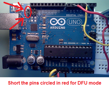
First you need to put your Arduino in DFU-Mode while it's connected to your PC. To do that, follow the image below:
If it's the first time for your PC to be connected to an Arduino in DFU-Mode, you need to follow these instructions to connect the Arduino to FLIP.
In Flip, first select ATmega16u2 in Device -> Select and press OK. After that, go into File -> Load HEX File and search for Joystick.hex you compiled earlier. Then press on the USB-cable in the top menu and select USB, then press Open. Now you are ready to flash!
Select Run in the bottom left corner to flash the .hex file onto the Arduino. When done, disconnect the Arduino from your computer and reconnect the TX & RX-Pins to the bridge.
To start a TAS file, simply start the clientTAS_GUI.py file (in the Arduino/utils folder). Make sure the TX & RX pins on your Arduino are connected correctly. Then connect your Arduino via USB to the Switch. After starting the program, a new window will appear - you will first need to synchronize with the switch, then load a TAS script and run it. You can also test the V-sync to check if everything is working correctly.
If you have trouble setting up everything or running scripts, feel free to ask on the Switch TAS discord server.
Thanks to MonsterDruide for the original repo, Shiny Quagsire for his Splatoon post printer, progmem for his original discovery and wchill for his SwitchInputEmulator, this project is based on his.