Repository navigation
Control GPIOs
This module makes extensive use of a character device. If you are not comfortable with them, check this page first. In order to communicate with GPIOs, we can build a character device to which we write and read data depending if we want to set a value (e.g. lighting up an LED) or read a value (e.g. read the status of a button).
Check the GPIO pinout of the board and choose a couple of pins to connect an LED and a button.
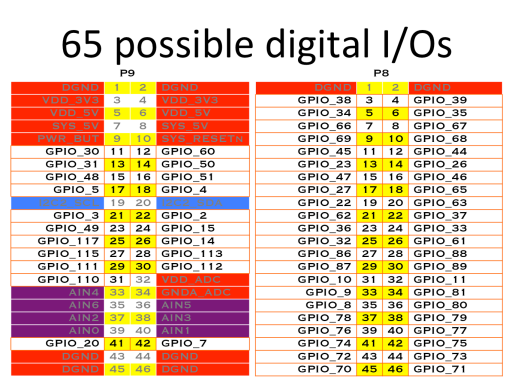
For the following example, I chose GPIO 49 (pin 23 on P9) for the LED and pin 117 (pin 25 on P9) for the button. Don't forget a pull-down resistor on the button and a current-limiting resistor for the LED.
We will engineer the LKM code around a basic character device (go build one if you haven't done it before!).
We start by defining some macros for the GPIOs.
#define GPIO_BUTTON 117
#define GPIO_LED 49
The open() and close() functions are exactly the same, and so is the file operations structure.