Programmable arduino chess clock with LCD and membrane keypad
- Easy to use
- 3d design similar to professional chess clocks such as DGT or LEAP
- Starts with a default time of 3:02 minutes and 2 seconds of increment
- Maximum time of 59:59 minutes
- To pause/resume just click the "C" button on the membrane keypad
- To modify each player's time first you have to pause it ("C") and then click "A" or "B" to modify white or black's time respectively, then enter the new time, for example, if you want to set the time to 12:30 minutes just click "1" then "2" and finally "3". When something finishes with "0" it isn't necessary to enter "0" but you can type it if you want.
- To change the increment(remember that starts with 2 seconds) of each player first the time has to be paused. Next you have to click the "D" button and click " * " or "#", whether you want to add seconds or minutes. Once this is done you will be able to type the increment. When you finish press "D" and then you will be able to resume the match.
- 16x2 LCD --> 1 unit
- Arduino UNO board --> 1 unit
- USB 2.0 cable type A/B --> 1 unit
- 4x4 matrix membrane keypad --> 1 unit
- pushbuttons (I used the micro limit switch pushbuttons, link at the end) --> 2 units
- 10kΩ potentiometer --> 1 unit
- switch --> 1 unit
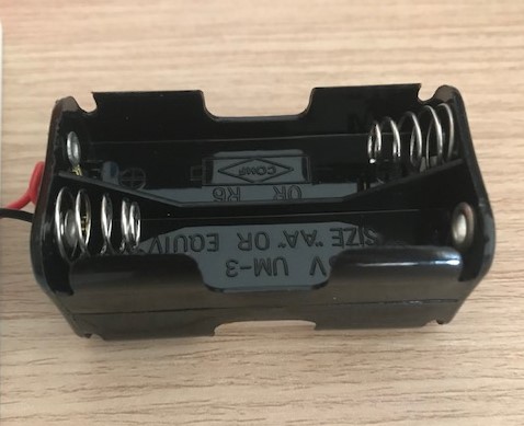
- 4 x AA battery holder --> 1 unit
- wire to connect everything
If you want to assembly all the parts into a compact chess clock, you can print my 3d parts. Read before the recommendations below to make sure the design fits correctly to your electronic components.
- You will need a specific pushbutton, otherwise it won't fit into the case, you have more information in the link below.
https://www.amazon.es/GTIWUNG-Interruptor-enrutador-Impresora-125V-250/dp/B08LD68FYQ/ref=sr_1_1_sspa?crid=3E748LCIT7XJA&dchild=1&keywords=pulsador+final+carrera&qid=1631032868&sr=8-1-spons&psc=1&spLa=ZW5jcnlwdGVkUXVhbGlmaWVyPUExQUxVMzlMTVhMSDJTJmVuY3J5cHRlZElkPUEwNzA2NjIxM1ZQTzk4Qk5CWTVLMSZlbmNyeXB0ZWRBZElkPUEwNTMwMjk1MVlZWDZTVko4VU0ySCZ3aWRnZXROYW1lPXNwX2F0ZiZhY3Rpb249Y2xpY2tSZWRpcmVjdCZkb05vdExvZ0NsaWNrPXRydWU=
- Your battery holder must be like in the image.
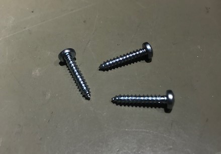
- The screws must be self-trapping, as the 3D printer isn't accurate enough to print the thread.
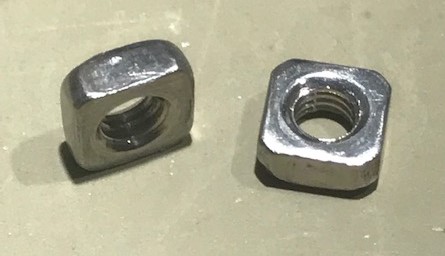
- There is a battery cover which you can disassemble it as many times as you want, but inside, there are 2 slots where you have to put 2 metric 3 square nuts.

-
Depending on the arduino board and the LCD you use, all holes may not be concentric, so first I recommend you to check the 3D design to ensure that all holes are as concentric as possible.
-
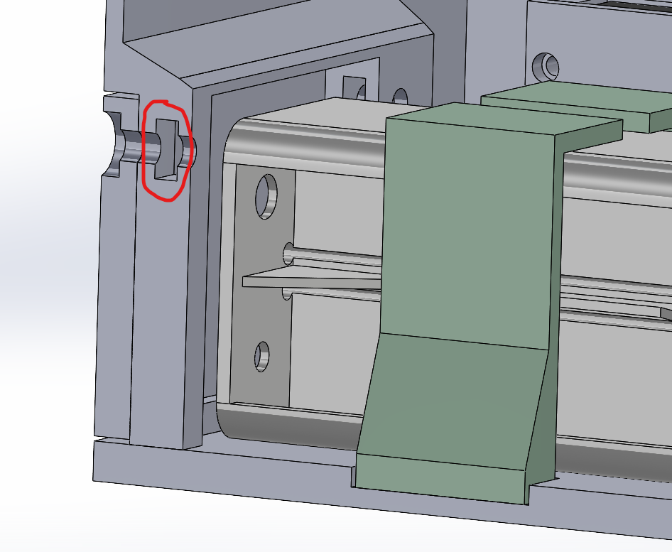
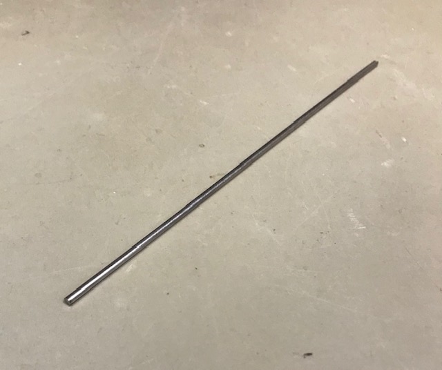
In order to fix the lever which you press to change turn, you will need 2 washers and a 2 mm diameter metal bar (57,5mm length). The metal bar has to be inserted inside the lever and then put the lever inside the case with the washers, finally you will be able to fix the lever with 2 small covers, like is shown in the next images.


-
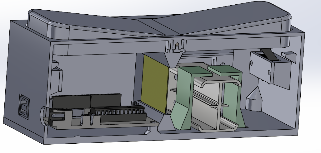
The yellow plate is used to help the lever return to its initial position, as the pushbutton shouldn't pe pressed all time. It has to be flexible, but not too much, and the dimensions are 35x47,75x0,5 mm.
-
The green parts which hold the battery have to be glued into the grooves of the base.