pinocchio UNIST robot club legacy
-
현재 유니스트 석박과정중인 황재박씨가 남겼던 유산이 모두 해체되었다. 고통받는 그의 노고를 기리고자 6족 로봇을 복원했다.
그러나 이전의 프로젝트에 비해 HW 부품만 같고, 회로와 펌웨어 및 제어가 달라서 다른 로봇이라고 할 수 있다.
시간이 지남에 따라 기술도 발전했기에, 이 프로젝트의 발전 가능성을 고려해서 몇가지 업그레이드를 했다.
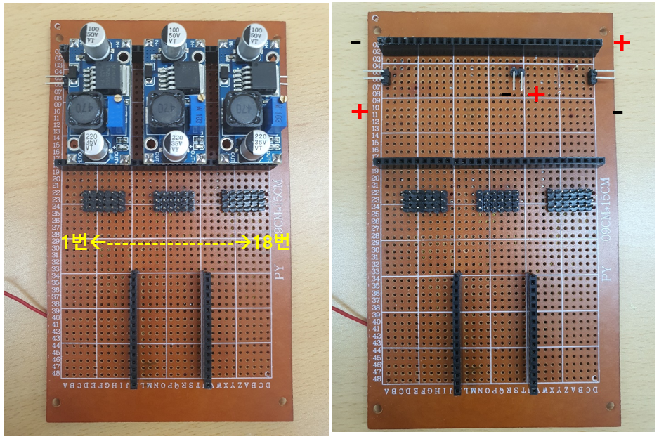
파워 서플라이로 사용하지 않고, 배터리로 안정적으로 전력을 공급하는 회로를 만들었다.
멀티쓰레딩이 가능한 보드를 써서 펌웨어 구성을 쉽게 했다. 블루투스 통신을 모터 제어와 다른 쓰레드로 분리했다.
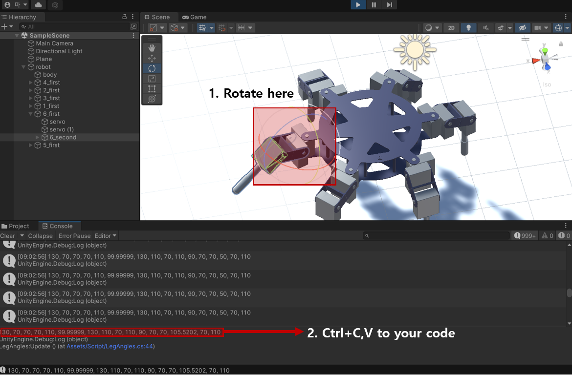
서보모터의 각도를 일일히 계산해서 코드에 사용하하는 방식이 아니라, 각도를 알아내는 용도의 유니티 프로젝트를 만들어 직관적으로 실험해볼 수 있게 했다.
-
The legacy left by Hwang Jae-bak, who is currently studying for a master's degree at UNIST, has been lost.
To honor his hard work, I decided to restore the 6-legged robot.
Compared to the previous project, only the HW parts are the same, the circuit, firmware and control system are different, so they are a completely different robots.
As technology has improved over time, I have made several upgrades considering the sustainability of this project.
Circuit that stably supplies power with a battery without using it as a power supply.
Instead of creating a time-sharing system through C programming, board capable of multi-threading is used to simplify firmware code.
Rather than calculating the angle of the servomotor by hand, I created a Unity project to find out the angle of the motor so that I could experiment intuitively.
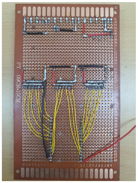
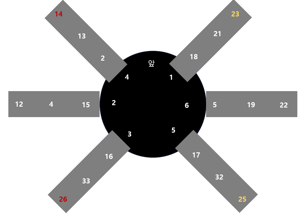
아래의 회로와 조금 달라졌다. PWM핀이 충분해서 ESP32를 보드로 사용했으나 timer가 16개가 있으므로 다리 2개의 제어는 별도로 설정해주어야한다. 그래서 그냥 물리적으로 쇼트를 시켜서 26번과 14번/ 25번과 23번을 같이 제어했다.
또한 GPIO 34, 35, 36, 39 핀은 인풋용이므로 사용할 수 없었다.
그러나 너무 간단하기 때문에 바뀐 회로나 회로도는 따로 첨부하지 않겠다.
The circuit below is slightly different from the actual one. The ESP32 was used as a board because there were enough PWM pins, but since there are 16 timers, the control of the two legs must be set separately. So I just physically shorted it and controlled the 26 and 14 / 25 and 23 together.
Also, GPIO 34, 35, 36, 39 pins are for input and cannot be used.

모터 위치와 핀 번호이다.
영상에서 보이듯 모터의 출력은 로봇의 하중을 감당할 수 있다.
- exec0: standing
- exec2: 4 posed walking
- exec4: FSM bluetooth control
- exec5: Idle state changed to withstand the load. Back, Turn states implemented
너무 단순한 구조이다.